Amiga 1081 Monitor from 1986
Please Note: The activities outlined in this article describe working with electronics that convert up to many thousands of volts. It is very easy to touch the wrong thing and cause permanent damage or death. If you are wanting to repair similar monitors yourself, please arm yourself with safety equipment such as an Isolation Transformer, and insulated tools. And read read read all about CRT repair before even attempting anything similar. Your family with thank you.
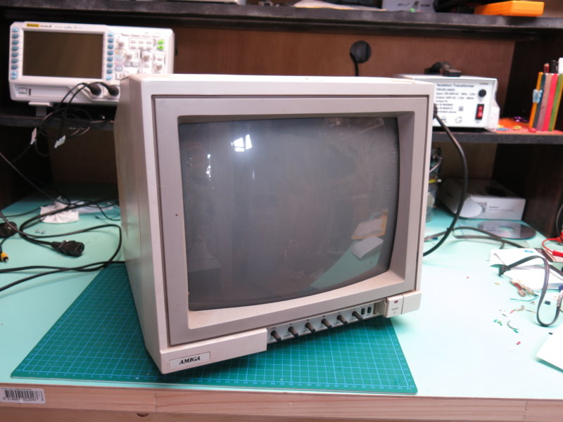 I've been looking forward to getting this on the bench for a while now. A friend gave this to me a while back when he sold off his Amiga 1000. I didn't know what state it was in. Like most Commodore monitors, these are worth fixing, with composite in, TTL RGB and SCART inputs.
First thing to do was check the standard power on test and see if the thing goes bang or puts out any weird noises or smoke.
The switch turned out to be dodgy which is super common for all monitors of this era. Pressing the switch wouldn't stay on. Holding it in powered the screen and the LED lit up. I could hear the high voltage, and was able to see a screen of sorts.
The high voltage sound seemed fine, and I appeared to have a raster. The screen was totally white. Or a pale white. Pressing the green button gave the screen the expected green tint. That seemed to show that the various guns are working in the CRT.
I connected up a Playstation 2 composite cable to the CVBS-IN and audio cable to the audio input. The audio worked fine, but screen was still white. This gave an indication that the main board is actually working and processing at least the audio portion.
It also indicated that the power supply was pretty much working.
Trying to rule out the actual CVBS-IN RCA socket, I tried a composite to SCART adaptor and connected the Playstation 2 to the SCART connector. Same result, white screen plus audio.
Time to open it up and have a poke around. Kidding of course. Once open, it was serious business time.

I was amused to see different sized screws. I'm probably not the first person here. Looking at the main board, I'm most definitely not first. There had been some touch up soldering on most of the ICs, and quite a bit on the CVBS-IN socket.
Before going on, I decided to see if I could fix the actual switch itself. Getting a replacement could take some time and I'd rather have it sorted now. Disassembling the switch took some time.
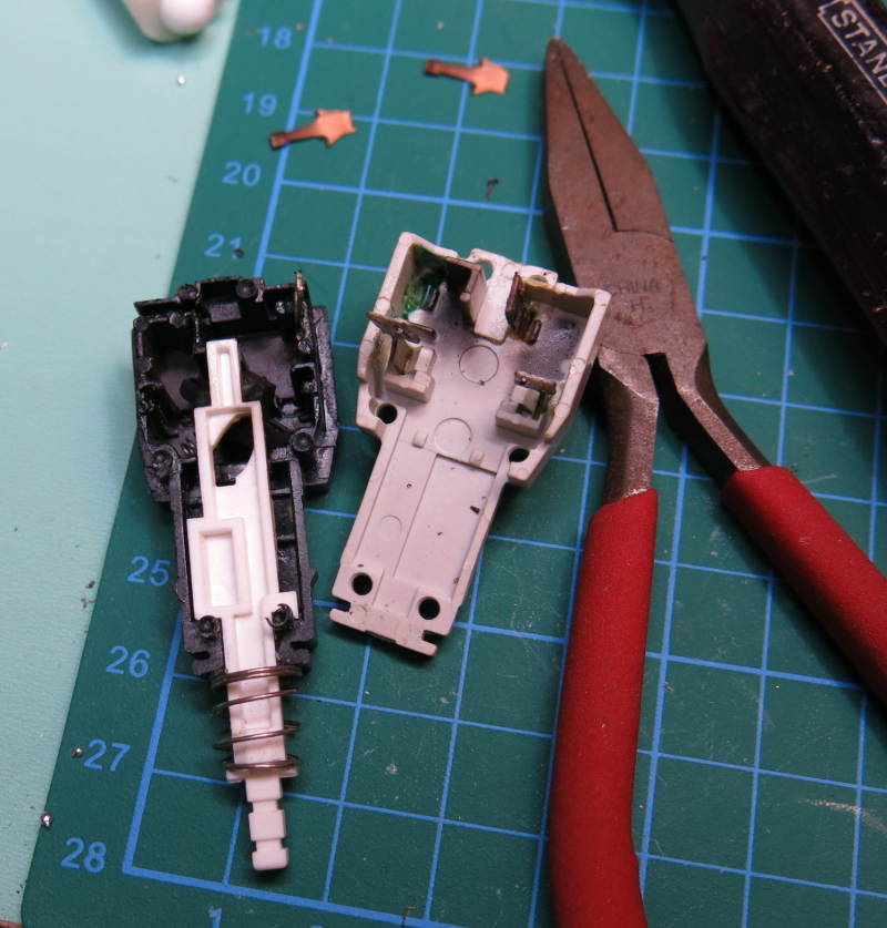
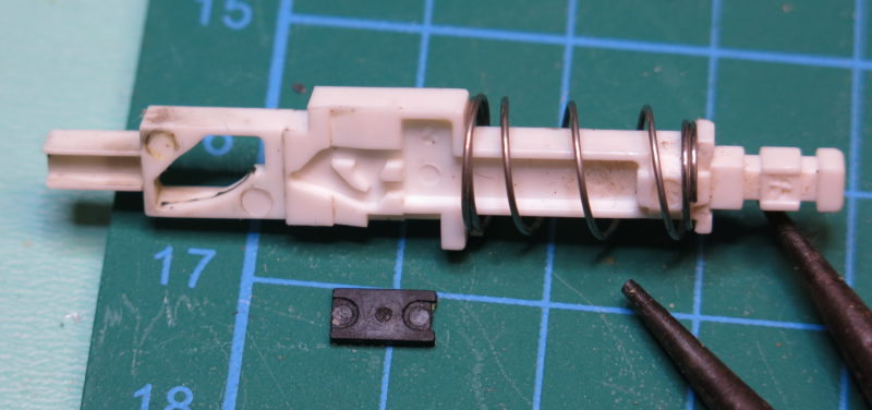
It took a while to figure out the internals of the switch and it appeared that perhaps a small nib had worn down. I spent a while (perhaps way too long) manufacturing a new nib. But it didn't really improve the switch and I decided to give that away.

Then I realised that I could cannibalise the switch from my 1084S-D1 monitor that is currently apart while I hunt down a replacement flyback for it.
They were a perfect match and I swapped them over. That 1084S switch is not too crash hot either, but it's better than the current one and will do until I can order a couple of replacements for both monitors.
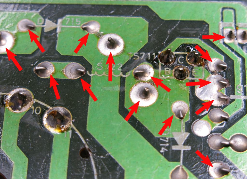
Checking over the neck board, I found plenty of dry joints. Refreshed those with new solder.
I turned my attention to tested the power supply, so that all rails show solid voltages.
330V DC on the primary filter cap looked all good.
I expected 25.5V DC on a secondary winding after the rectifier diode. Got 20mV. Expected 125V DC on the secondary winding after the rectifier diode. Got 60mV. Expected 15.8V DC on the secondary winding after the rectifier diode. Got 4mV.
Didn't make sense considering many of the monitor's features were working.
Checking all components after the filter cap.
Here's where things started going wrong. Diodes and transistors seemed to test open, or out of spec. But de-soldering or testing off the board seemed to show them as fine.
Expected voltage on one transistor was -1.65V but the schematic says should be -4.5V.
Resistors seemed to be all off, or different every time I tested them.
But in all this, except for video, the monitor was working.
Things just seemed to stop making any sense. So I de-soldered the primary side of the transformer to isolate the components and get more accurate readings.
This seemed to make things worse. All resistors seemed to fluctuate their values wildly. Taking the resistors off the board (who ever needs to do this?) sometimes seemed to improve things, but not always.
I'll cut to the chase. It was my red multimeter lead. A break in the tip somewhere was losing continuity and giving the wild fluctuations in all readings.
New test leads, re-soldered everything back in place.
This time, I got the expected 25.5V, 125V DC, and 15.8V DC voltages on the secondary winding after the rectifier diodes.
Then I started looking over the main board for more signs of poor solder joints.
C505 was poorly soldered. In fact it's legs were wiggling free, and just hanging on. This part looks to be a replacement. It's an orange electrolytic capacitor, the only one like it on the board. And it's a little fat too.
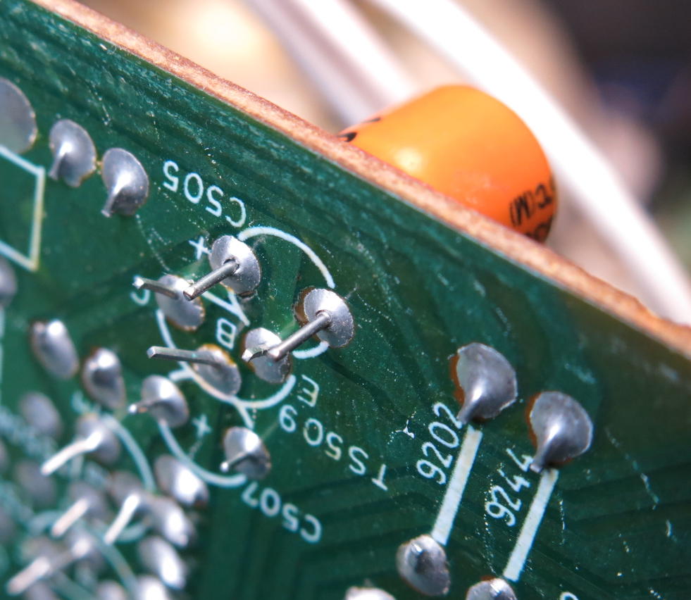
Rather than re-soldering it back in, I took it out first to double check it's value. It tested fine. Re-soldered back in place. That was a pretty glaring issue so I thought it was a good time to see if the screen was resolved.
Reassembled without the de-gauser connected, and turned it back on.
Got sound, and same white picture, but this time, the vertical was a little less stable. This was surprising as I would have though the capacitor should not have made things worse. Could have been completely unrelated.
I started suspecting caps or the TDA3505. Or 12V regulator?
Noticed a few early signs of cracked joints on the edge board connector. Re-soldered all pins.
Next, to measure all 12V points
C492 from the IC404 12V REGULATOR had a good even 12V. Great sign.
Noticed on a closer inspection quite a few solder cracks on the main board. Re-soldered all of them right across the entire main board.
Using the schematic (see References below for all the versions of schematics available) it was time to trace power rails between ICs.
I measured all the voltages stated on the schematic for IC502 which is a TDA 3505.
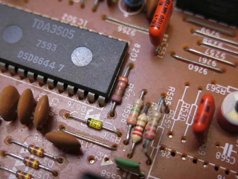
All measured very close to the schematic except for pin 11. This should have measured 11.6V, but I was only seeing 10mV, pretty much nothing.
Went for another reassemble since fixing up many cracked and sad joints. This time the raster was very stable, but still nothing but a white screen.
I found a superior schematic with voltages marked in all regions. This is the Phillips CM 8533 service manual which is exactly what the Amiga 1081 is.
I traced the dead voltage line from Pin 11 of the TDA 3505. It was 0V until I got to the other side of R232 and the 12V was there! I think I found my component! I was about to remove the resistor from the board to double check it, but something looked really different, not quite right. Looking at the R232 on the schematic, and what I had here on the board was totally different.
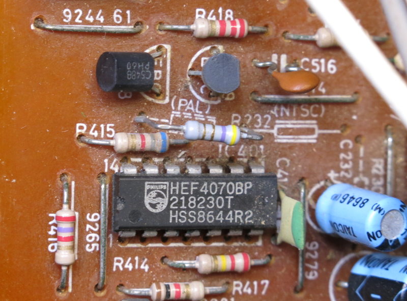
Looking at the print on the PCB, the R232 could be fitted in one of two places. One for PAL or the other spot for NTSC.
NTSC is noted on the board, but for PAL, the resistor must be slightly moved into the next position on the PCB. R232 PAL is 12V one side and 11.7V the other. So that's probably why pin 11 on IC 502 shows nothing because PAL in connected and NTSC is disconnected. They have separate circuits bridged by the R232 safety resistor.
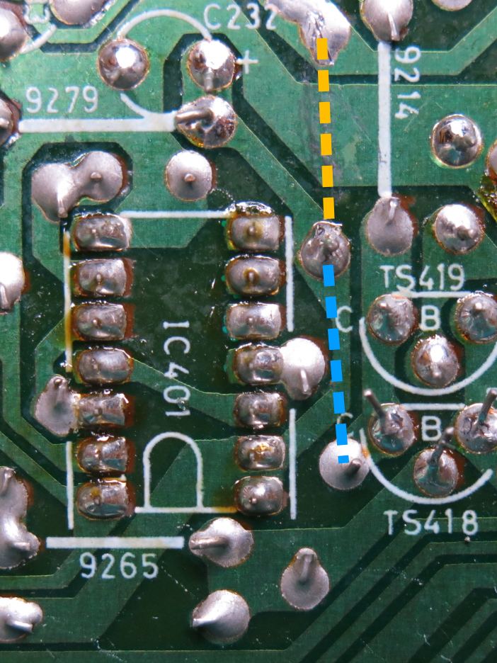
In the image below, the orange line is where the R232 is placed for NTSC, and the blue is where the R232 is placed for PAL.
What is interesting is that every schematic I could lay my hands on is configured for 250V which is suitable for Europe and Australia, yet the circuit in the schematic is configured for NTSC. And therefore the voltages to test are also shown for this active NTSC circuit. So I am not sure why this is.
I have not found a schematic that shows the R232 configured for PAL.
Checking over all the voltage test points I could reach (I got sick of pulling the board in and out for testing), they all seemed to be fairly much in the expected range. And the voltages in the PAL configuration were not marked on the schematic, so I was satisfied that there should be differences in that area. Perhaps the main board was largely fine.
I then noticed that one of the ground solder joints of the CVBS-IN RCA socket had a really bad crack and was lifting from the PCB. Might not be enough to break contact with ground as there were other ground pins, but it looked really dodgy and I didn't notice the damage earlier.
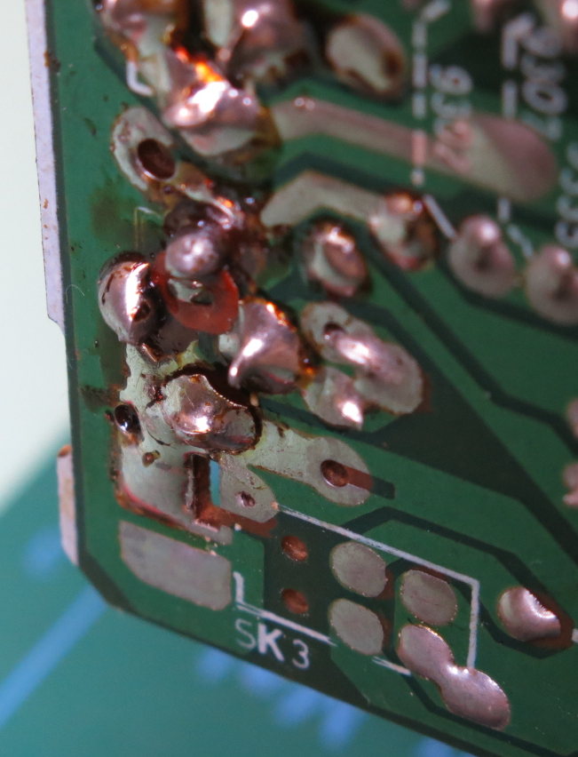
Doing a quick continuity check, I discovered that the composite centre pin and ground on video-in appeared to be shorted.
I don't like to trample on another brother's previous work, but this area of rework was just a little too messy.
I removed as much solder as I could and took the RCA socket off the board. Tested fine, no short in the socket itself.
A close look at the area without the socket revealed a round section of trace had lifted off the board and folded back down onto the ground trace. That was the cause of short on the board.
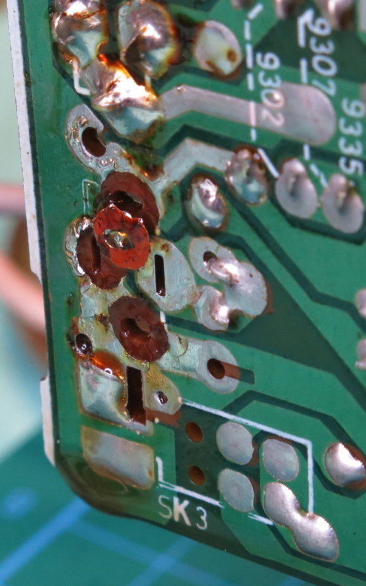
I suspect what had happened was that the socket had been removed at some point. And when pushed back into the PCB, all the ground pads had been ripped out. One had folded over. The repairer hasn't noticed this, and had just soldered over everything with so much solder to try and compensate for the loss of pads.
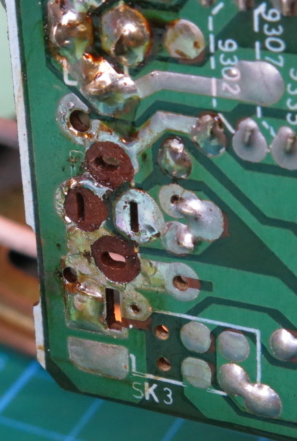
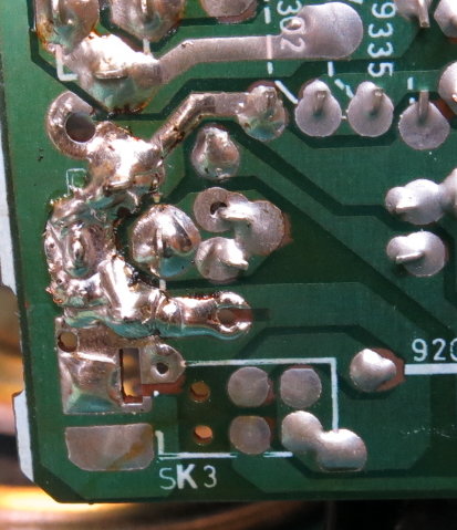
I managed to rescue two of the broken pads and superglue them very carefully back into the PCB.
I replaced the missing third pad by using a small section of solder braid to add stability. Soldered the socket back in and the short was gone.
Time for another power up test. No change, white screen. Darn.
Next was to look at the video signal test points shown on the Phillips schematic with the oscilloscope to measure the analogue video signal. First was a test on the actual video source on the incoming plug. Yep, there was a signal as expected.
Test point 10 on the board was also a composite signal. Happy with that.
It was at this point when getting something from the shelf, I noticed that I had a picture! What? When did that occur? I touched the cable at the socket and the picture went back to a white screen. Ah ok, there is a break remaining somewhere.
The connections of the socket to the PCB should have been pretty solid, so I suspected the socket itself. I de-soldered the socket again, and reconsidered something that bothered me when I first looked at it: it was heavily tarnished.
Even with a multimeter on one side of the inside positive connection, and the other on the positive leg, continuity was extremely poor. I didn't have a spare so I used some alcohol and wire brush to clean the positive pin and assembly until both ends gave good continuity. Then a little squirt of WD-40 to protect the exposed metal from further tarnish.
Continuity was then fine. I placed it back on the PCB (very carefully) and powered up.
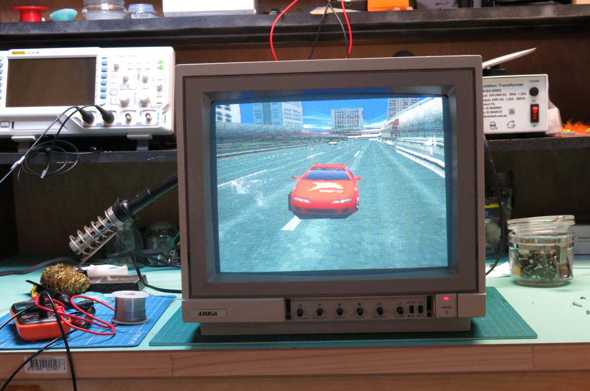
And ended up with a fantastic looking picture. Some minor colour and H/V position adjustments and I now have an Amiga 1081 monitor back in service and rescued from the pile for another day.
Really pleased to get to the bottom of this one. An interesting repair with a lot of twists and turns.
References
- https://freeservicemanuals.info/en/servicemanuals/viewmanual/Philips/CM8533/CM8535/ (the finest version of the schematics I have found)