Table of Contents
Generating VGA with an FPGA (Verilog)
 Generating a VGA signal can be a rewarding achievement as an FPGA project. There are loads of explanations and illustrations online on how to generate VGA signals. But sometimes the concept is not clear.
I'll attempt to introduce each concept as plainly as possible.
Our goal
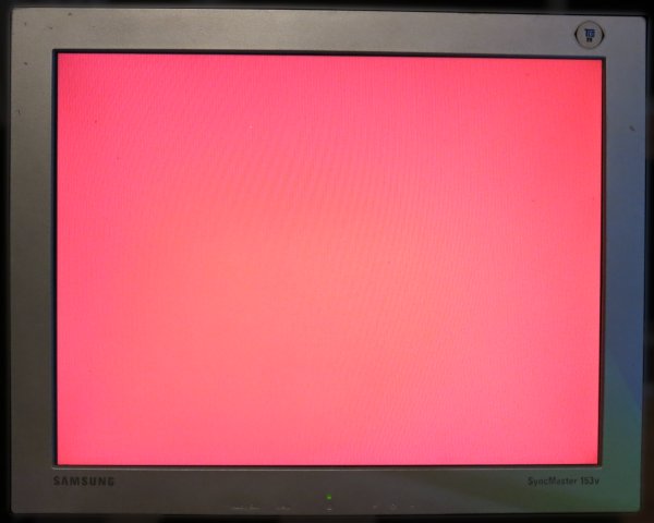
We are looking to output a 640×480 image at 60Hz, all red pixels.
Equipment
I'll be using The GoBoard as my FPGA dev board and a small VGA LCD monitor.
The GoBoard runs at 25MHz which is almost spot on for generating VGA signals.
I strongly recommend reading the VGA tutorial over at the GoBoard site first as it explains many concepts that I won't bother repeating here.
VGA Pins
There are five pins that are important for generating VGA, but we will only be interested in three to keep things simple:
- Red pin
- HSync pin
- VSync pin
Active area and Inactive area
A VGA mode of 640×480 actually sits inside an Inactive Area that is 800×600 pixels.

In the above image you can see the active area is made up of 640×480 red pixels, which is pixels 0 to 639 horizontally and 0 to 479 pixels vertically.
Horizontal Sync and Vertical Sync
Let's put areas aside for a moment and look at sync.
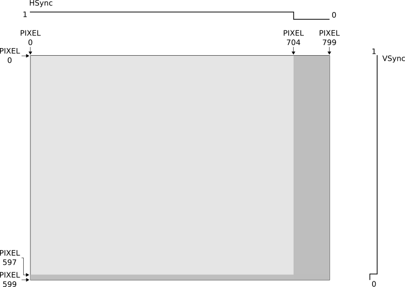
In the above illustration, the dark grey regions are where the horizontal and vertical sync occurs.
As recommended at http://tinyvga.com/vga-timing/640x480@60Hz, the industry standard width of the horizontal sync is 96 pixels. This means that across the entire 800 pixels width, the HSync signal needs to remain high until pixel 704 and then low until pixel 799.
In the same way, the VSync signal needs to remain high until line 597 and then low for the remaining two lines until 599.
Colour signal
Now that we have sync sorted, and we know about our active area, we will only turn on the colour (on the red pin) when we are less than 640 on the horizontal and less that 480 on the vertical as illustrated here:

The Verilog
Now we know enough to get a first result from your VGA monitor. Here is the test code:
top.v
`include "vgaprocessor.v"

module top
    (
        input i_Clk,
        output o_VGA_Red_0,
        output o_VGA_Red_1,
        output o_VGA_Red_2,
        output o_VGA_HSync,
        output o_VGA_VSync
    );

    wire w_redColourPin;

    VgaProcessor processor
    (
        .i_Clk(i_Clk),
        .o_HSync(o_VGA_HSync),
        .o_VSync(o_VGA_VSync),
        .o_Red_Colour_On(w_redColourPin)
    );

    assign o_VGA_Red_0 = w_redColourPin;
    assign o_VGA_Red_1 = w_redColourPin;
    assign o_VGA_Red_2 = w_redColourPin;

endmodule
vgaprocessor.v
module VgaProcessor
    (
        input i_Clk,
        output reg o_HSync = 0,
        output reg o_VSync = 0,
        output reg o_Red_Colour_On = 0
    );

    localparam TOTAL_WIDTH = 800;
    localparam TOTAL_HEIGHT = 525;
    localparam ACTIVE_WIDTH = 640;
    localparam ACTIVE_HEIGHT = 480;
    localparam H_SYNC_COLUMN = 704;
    localparam V_SYNC_LINE = 523;

    reg [11:0] r_HPos = 0;
    reg [11:0] r_VPos = 0;

    //step pixel position throughout the screen
    always @(posedge i_Clk)
        begin
          if (r_HPos < TOTAL_WIDTH-1)
            begin
                r_HPos <= r_HPos + 1;
            end
          else
            begin
                r_HPos <= 0;
                if (r_VPos < TOTAL_HEIGHT-1)
                  begin
                    r_VPos <= r_VPos + 1;
                  end
                else
                  begin
                    r_VPos <= 0;
                  end

            end
        end

    //Horizontal sync
    always @(posedge i_Clk)
        begin
          if (r_HPos < H_SYNC_COLUMN)
            begin
                o_HSync = 1'b1;
            end
          else
            begin
                o_HSync = 1'b0;
            end
        end

    //Vertical sync
    always @(posedge i_Clk)
        begin
          if (r_VPos < V_SYNC_LINE)
            begin
                o_VSync = 1'b1;
            end
          else
            begin
                o_VSync = 1'b0;
            end
        end

    //Colour On/Off
    always @(posedge i_Clk)
        begin
          if ((r_HPos < 640) & (r_VPos < 480))
            begin
                o_Red_Colour_On = 1'b1;
            end
          else
            begin
                o_Red_Colour_On = 1'b0;
            end
        end

endmodule
That should give you a result that looks like this:

We have a display which is great! But it's in the far top left corner.
Back Porch and Front Porch
I've avoided this topic until now because it clouds the issue. We can get a working signal without knowing anything about it. However, in order to centre the 640×480 image, front porch and back porch need to be taken into account.
If instead of switching the colour on between 0 and 639 on the horizontal, and 0 and 479 on the vertical, what if we offset it?
What if the colour signals were turned on between 50 and 690 on the horizontal, and between 33 and 513 on the vertical?
This would effectively create a gap to the top and left (a horizontal back porch, and a vertical back porch).
Then you have the remaining gap on the right and bottom after the active area. This is a horizontal front porch and a vertical front porch.
Let's now apply this to the code. Replace line 70 in the vgaprocessor.v file with:
if ((r_HPos >= 50 & r_HPos < 690) & (r_VPos >= 33 & r_VPos < 513))
Shifting the colour positions to change the porch will centre the active area. You will get a better result that looks like this:
Back and Front Porch is not so confusing after all.
Please note that the values chosen above are in agreement with those recommended at the GoBoard site: https://www.nandland.com/goboard/vga-introduction-test-patterns.html. I have confirmed that these values do a much better job than the industry standard values of centring the display each LCD monitor I have tested.
Next steps
If this helps you, I would love to hear about. Feel free to drop me a note with the Contact link above. Hopefully this makes working with VGA more approachable. From here you can continue on with any number of the following great articles that do a fine job of introducing how VGA works.