Minimum setup for a PIC16F1455 on a Breadboard + PICkit3
If you need a quick setup for the PIC16F1455, fast wiring and code to check output from a pin, this article is for you.
Firstly, the breadboard layout:
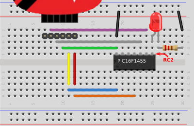
Shown is the 6-pin header where you connect your PICkit3.
PICkit3 Pin 1 - red wire -> orange wire  -> MLCR on Pin 4
PICkit3 Pin 2 - yellow wire -> blue wire -> VCC on Pin 1
PICkit3 Pin 3 - green wire -> Ground on Pin 14
PICkit3 Pin 4 - grey wire -> PGD (ICSPDAT) on Pin 10
PICkit3 Pin 5 - purple wire -> PGC (ICSPCLK) on Pin 9
Connect an LED and 100 ohm resistor from RC3 (Pin 8) on the PIC16F1455. Run the ground side to PIC16F1455's ground pin (Pin 14).
That's all you need to wire up the breadboard. Ensure to power the board using the PICkit3.
Fire up MPLAB X and start a new project based on the PIC16F1455. Create a new C file under the source folder. Add the following code:
#include <stdio.h>
#include <stdlib.h>
#include <xc.h> //include for all pic projects

int main(int argc, char** argv) {

    TRISC = 0b00000000; //set all pins on Port C to Output
    PORTC = 0b00000100; //set pin RC2 to 5v or ON.

    return (EXIT_SUCCESS);
}
In the TRISC above, all pins are set to output with 0. With the PORTC setting, the third pin, or RC2 is being turned on.
Compile the code and use MPLAB IPE to send the resulting .hex file to the microcontroller.
The LED should turn on. If not, check the orientation of the LED, or check the pin with a voltmeter. There should be 3.5v to 5v on it.
That's it. You're up and running.