Samsung 32" S32D850T Monitor Repair
I had a 32“ Samsung monitor on the bench from a friend at work who only used it for four years before the power went out and wouldn't turn on again.
On one attempt to turn it back on, there was a small pop and that was it.
Once I got it into the workshop, I attempted a power on and got a pop as well.
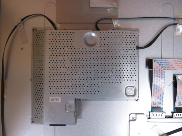
Dismantling wasn't too difficult although removing the back cover and rear panel took some time. Like many LCD monitors, it's held together with tabs. This one was better than most.
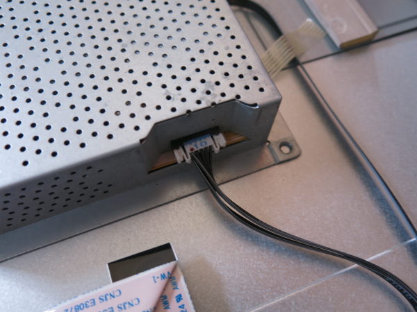
The power supply board is held behind a metal shielding panel. There are three connectors to remove and then the metal shield can be lifted out at the top. No screws used.

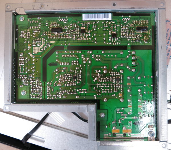
Flipping the metal shield over shows the power supply PCB. This board has a model code of L32S0X and a part number of BN4400750A.
Fuse was blown. Seemed like it might be an easy fix, especially if a small external surge is all that's responsible. Although usually something else on the board is more likely to have caused the fuse to blow.
I connected the board to the isolation transformer and turned on the power. Another pop. I hooked up a camera and darkened the room in the hope that I might be able to visually identify the part that was popping.
Unfortunately it appeared that I had used up all my chances. There were no more pops or any other life left in the board at all.
And to top it off, I had blown the fuse in my isolation transformer.
Once replaced, I had to replace the fuse on the power supply PCB. It was a fast blow 6.3 amp fuse which I could get locally but not at the right size.
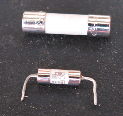
It wasn't crucial to have the right size as there was enough space on the board to jimmy-ed up some leads and replaced the old one with my modified fuse.

Once replaced I tried the board again with power. No pop again, but still no life. And I blew another fuse in the isolation transformer. Darn. These are $1.80 a pop (no pun intended). But interestingly, the fuse on the board was still fine.
Replaced the fuse in the isolation transformer again.
It was time to start looking at the individual parts on the board to locate the problem, starting with the AC in.
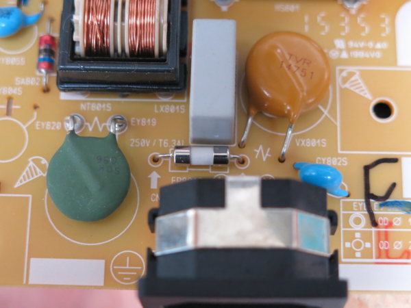
I couldn't see anything wrong along the AC lines: caps appeared to be OK, inductors too. Safety thermistor and varistor both worked fine. All diodes fine.
There was another component on the board here that was a bit of a mystery. It looked like the love child of a zener diode and a resistor. It had a glass body like a zener, but stripes like a resistor.

There was continuity across the leads. Is this a shorted component? Or is it meant to be this way, like a fuse? It was really difficult to find anything online to describe what this was. I finally found references describing this as a Gas Surge Discharge Tube.
Also found a lot of information on them, written by wordy scientific types. Not overly digestible. And after reading everything I could, I still couldn't get a straight answer as to whether or not there should be continuity across it's leads in a good state or damaged state.
I had to give this some research as the board had given several pops by now and so it was not clear if this component could be causing the issue.
The other thing I could not find was a standard chart or guide to Gas Surge Tube colour bands. I tried a few datasheets of particular brands of tube. It appeared that colour bands mean something per manufacturer, but I am still to confirm this.
Since then P.Remaker has been in touch and got some great answers on these “Sparkgap Arrestors”, what is it, and it's designator and it's symbol. You can get more in-depth reading here. With all that said, this part is doing more to save your monitor than being the cause of your fault.
Everything on the pre-rectified AC side appeared to be OK, so was time to move to the rectifed side and see if the issue was there instead.
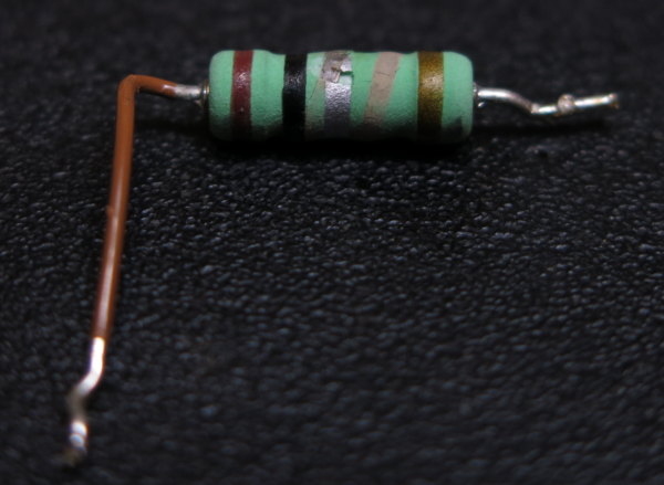
Discovered the RP829 resistor had blown badly. At first I thought there was an extra tan coloured band on the resistor, which made the value shown on it not right. But under magnification I could finally see it was not a tanned band, but rather the internally cooked resistor burnt on the surface.
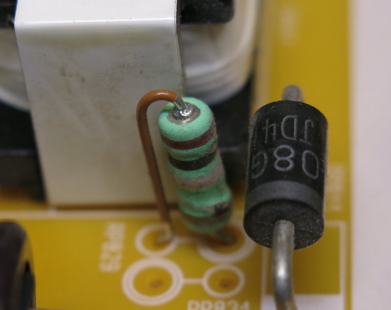
It was clearer once out of the board. Suffice to say the resistor was dead, no continuity at all. The band colours are Brown, Black, Silver. Then tolerance band is Gold, making this 0.1 Ohm.
Replaced it. Still no power, and no pop. But I did lose another fuse in the isolation transformer. Good grief.
Ok so clearly there was a short somewhere on the rectified side.
The Bridge Rectifier is the first thing in the chain, so best to start at the beginning. Tested bad in-circuit, so I ordered a replacement.
The new rectifier arrived in the mail.

The pin holes for the existing rectifier were interesting, they looked like a soldered claw. Made de-soldering the old rectifier quite difficult. I got it out, but the legs were pretty mangled.
But what a dope I was. Rectifier was OK after all. I should have tested it off the board before ordering parts. Oh well. I comforted myself that perhaps all the shorting on the board might have reduced the life of the rectifier. So swapping was probably a good idea anyway.
And of course, it made no difference to the PCB. Still blows the fuse in my isolation transformer. Glad I had a pack of 10 fuses, grrrr.
Ok, better track the source of this short more carefully.
Testing across the CP811 capacitor showed a short, both sides having continuity with ground. Again easy fix?
Tested the cap out of board: nothing wrong with it. There's still a short. Moving on…
The LP811 inductor at fault? Now this part (SC-141127EN) had me really confused. It was labelled L like an inductor, but it appeared to be a transformer.
If it's a transformer, the coil of the primary is used to pass current on the positive rail. Only the first pin of the secondary is connected to the negative rail. The centre tap and end of the secondary are not connected on the board.
Bizarre. Are they using one side of the transformer as an inductor along the primary side? Then why connect one pin of the secondary the negative at all? A puzzle for another time maybe.

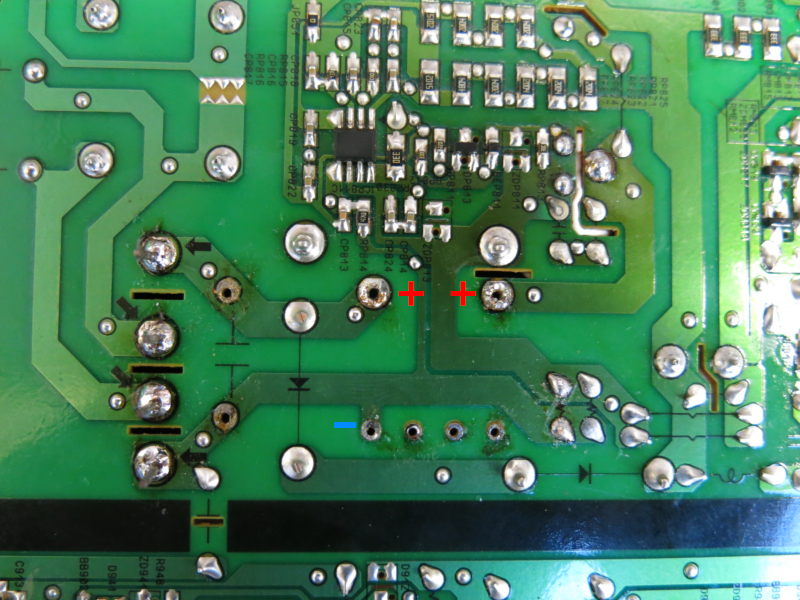
With the inductor/transformer out of the board, it tested fine. There was no more short.
Removing the part removes the short. But testing the part, there is no short between that primary and secondary leg.
![]()
So then perhaps it is not this inductor/transformer. Another component up the chain must be shorting.
I soldered the two primary legs back onto the board to complete the positive rail. Yep, the short returns but by leaving the secondary leg de-soldered, I know it's not this transformer/inductor that is performing the short.
Certainly the next component is a KF12N60 MOSFET which was also the cause of a fault in the same board repaired by Сергей Николаевич, a Russian guy here: https://www.youtube.com/watch?v=mWP2WTvkQaM
I had been suspecting this component earlier considering it is a MOFSET and connected to a heat sink. But I had hoped it was fine due to the fact that I wasn't too keen to dig it out of the mound of white silicone that it was buried under.
![]()
Took the MOSFET out and the short is gone. But we've done this dance before haven't we?
Using the KF12N60 datasheet, I tested the part out of the PCB and it's just not good at all, all legs are shorted. Really bad.
New part on order.
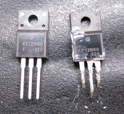
Five new MOSFETs arrived in the post. No shorts. All tested beautifully. I purchased these from Aliexpress here. Parts are hard enough to get anywhere, and these worked well enough for me. Be sure to select KF12N60 TO-220F so that you order the right MOSFET.
Interesting to note, all the new ones had a different forward voltage from 0.5, to 0.8. I used the 0.7 one.
Quick check on the board, seems no more shorts. Time to power the board up.
Received a note from Dave P who performed the same repair but used a FDPF15N65 (15 A, 650 V, N-Channel MOSFET by ONSEMI in a TO-220F package), and is working well.
Turned on: no bang. Isolation transformer didn't blow a fuse. That's something!
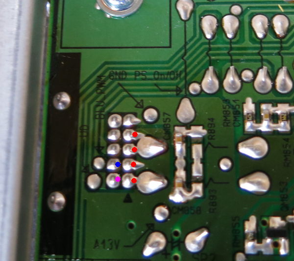
Tested the cold side output pins. I got the expected 4 x 12.8V pins, 1 x 2 volt and 1 x 3 volt output pins. I think this is a winner!
Time to try it back in the monitor.
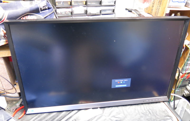
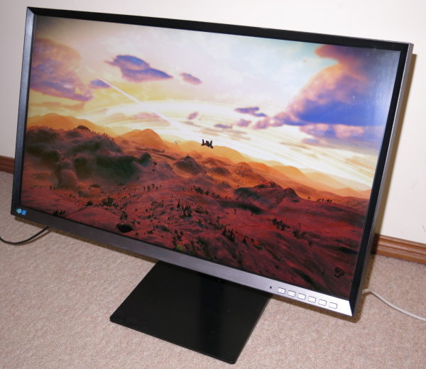
Fitted everything back together and powered on. Totally wrapped to see the screen power up and display both a “signal disconnected” message and a menu.
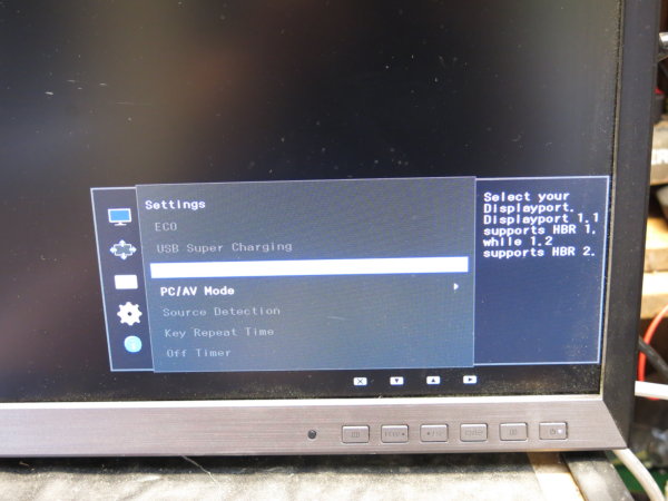
Finally, hooked up an HDMI cable and got a brilliant 2560 x 1440 resolution display.
So that's a winner, job done.
Other Successes
Nathan B, Nicolas S, Dave P, Jan.B from Germany, and Frank from Germany have been in touch to let me know that they have all managed to get their S32D850T's going again.
I also received a really nice note from Karen and Danny Ellis of Mend It, Australia who used the article to help inspire their repair. Theirs was set as a repair subject for the up and coming International Repair Day 2021.
You can see the video showing the analysis of their repair on Facebook, Twitter or Instagram.
Mend It, Australia was recently a featured speaker at the Australian Repair Summit in Canberra during 2021.
I always love to hear if this repair helps you. Please always get in touch if you managed to get your monitor going or need some advice.