This is an old revision of the document!
Table of Contents
Electronic Component Testing Cheatsheet
When doing a repair job, it's nice to have a handy testing cheatsheet for a range of electronic components. So far I haven't found one, so I created my own here which covers everything from very basic fuses and resistors to MOSFETs, even Gas Arrestor Tubes. All using a multimeter and other tools. I've tried to cater for absolute beginners to intermediate hobbyists.
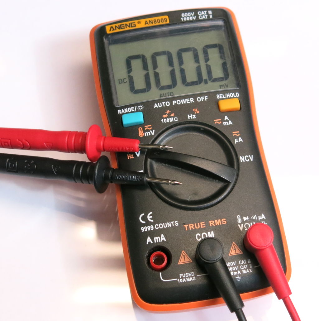
My favourite tools are the Aneng AN8009 multimeter and GM 328 component tester. You can find them both on Aliexpress.

One last thing: Any values shown in the illustrations are vague examples only.
Fuses
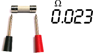 The most simple of tests. Switch to resistance setting or continuity and put a probe at each end. Low resistance around 0Ω will indicate a good fuse. If you have a continuity setting, the multimeter will beep for you. If you have no beep, or you have
 OL (Open Line) the fuse is bad.
(See here for other interpretations of OL but for this context, Open Line makes the most sense)
Resistors
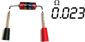
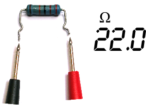 Set the multimeter to the ohms (Ω) reading and apply a probe to each end. Have a resistor chart handy to compare the colour code to the reading on your multimeter.
An OL reading means open line or broken connection. No current will pass, so it's a bad resistor.
An almost 0Ω reading is a short. Of course, there are very low value resistors, for example BROWN BLACK SILVER GOLD, totalling 0.02Ω, so always check the resistor chart to be sure.
Switches
You can never under-rate the testing of a switch. Switches can break: it's continuity can fluctuate. A switch can be normally open (the most common type) or normally closed.
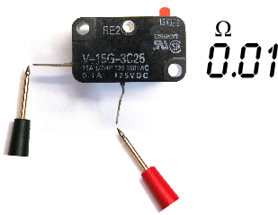
The continuity tester on your multimeter is the mode to use.
- If it's a normally open switch, ensure there is only continuity when it is pressed.
- If it's a normally closed switch, ensure there only continuity when it is not pressed.
An example of an interesting switch break in a recent dishwasher repair: with a microswitch that would click when pressed… it sounded like it was activated, but unless you pressed it further, there was no continuity. Needed replacing.
Capacitors
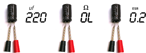
You can test for a short on a capacitor, on the PCB, using the resistance or continuity setting. Put a probe on both ends and if there is a very high ohms reading into the MΩ and finally to OL or open line then the cap is not shorted.
If there is a low resistance across the terminals, then you have a shorted capacitor which can allow damage to other components.
Beware of false positives. Parallel components can look like shorts so remove the cap and test it if unsure.
For capacitance tests, always best to test off the PCB if possible, though you can be lucky on the board. Use the capacitor test on your multimeter if you have one, and if you get the expected reading in nano-farads or micro-farads, then all well and good.
For ceramic caps on the board, sometimes I like to test these using a continuity test. Placing the probes at either end, there will be a short beep at the cap charges, and will stop when it reaches capacity. Swap the leads around and it will beep again until it reaches capacity.
If you get an unexpected readings for any cap, remove from the board and try again after discharging it.
ESR tests can also be performed with an ESR meter while the component is on the board. If the values look pretty much around the values on the table printed on the meter, you are likely to be OK. You can also dig into specific datasheets to check exact expected ESR values, but it's unlikely to be the cause of a fault if it's in the range.
You can also use an inexpensive GM-328 to check both capacitance and ESR in one go. But the component needs to be off the board and plugged into the tester. Good option if you are still not sure.
If you cannibalise parts for repairs, here's a good reference for some top quality brands to keep an eye out for. Suntan brand caps are very poor quality.
Finally, here is a great site for interpreting capacitor markings and one for converting capacitor values and units.
Inductors
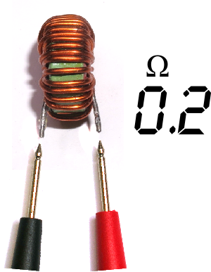 Using the resistor setting, put the probes on either end of the inductor. There should be an initial reading that quickly drops to 0Ω. This means the inductor is OK.
If you get OL, you have a break in the inductor and it is bad.
Diodes AND LEDs
Use the diode setting for this test.
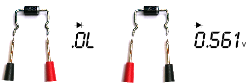
Place the positive probe at the end without the line marker. Place the negative probe on the end with the line marker. There should be a reading typically between 0.2V and 0.7V which is the amount of forward voltage the diode needs to start passing current. So that reading indicates good in that direction.
Swap the leads and you should have a reading of 0L indicating no current can flow in that direction. Which is good.
You can also test for a short by using the resistance setting. If you get a very low reading around 0.01Ω etc in either direction, you have a shorted out diode.

Testing LEDs (which are diodes too) is fun with a multimeter because you can see them light up with the correct orientation.
Sometimes you can get false positives with parallel components, so remove the diode from the board to test if in doubt.
BJT Transistors
NPN transistors can be tested by first searching for the part number online to ensure it is an NPN. Locate the Base pin if it marked on the PCB. Otherwise find it by locating a datasheet for it.
Use the diode setting for this test.
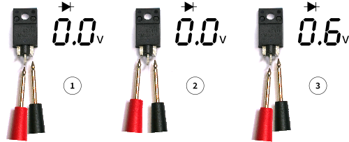
Put the positive probe on the Base and the negative to the Collector and Emitter in turn. Both of those should show a forward Voltage of somewhere around 0.5V.
![]()
Switch the probes around with the negative on the Base and positive to either the Collector and Emitter pins. Both should show OL.
Finally, positive probe on the Emitter and negative probe on the Collector will show OL. Reverse should show OL.
MOSFETs
For MOSFETs, you'll need to search for your part to identify which pins are the Gate, Drain and Source pins.
Place you finger on all three pins for a moment to de-charge the MOSFET. MOSFETs have a little capacitance in them which is handy for the test.
Switch to diode setting.
Place the negative probe on the Source pin. Touch the Gate pin very briefly using the positive probe. You may see a few numbers display briefly in the multimeter output.
The MOSFET will now contain a small charge.
Touch the Drain pin and you will get a reading of something around 0.9V depending on the MOSFET.
You can de-charge / reset using your finger across the three terminal and repeat the test. If the above behaviour is not given, further investigation might be required, but the part should be suspected.
If you get no response from the MOSFET at all, ensure you have good contact from probe to pin.
Reversing the test after resetting:
Positive probe to Source, and Negative probe to Gate should show OL.
Positive probe to Source, and Negative probe to Drain should show something like 0.5V and this cannot be cleared using your finger across the terminals.
Of course, MOSFETs to vary, so check your datasheet (a topic for another day).
Gas Glass Surge Arrestors / Gas Glass Discharge Tubes
 I include this because they look like a cross between a zener diode and the colour bands of a resistor. Little is written about them, but they can be located in some switch mode power supplies.
Switch to continuity mode.
Connect the probe at both ends.
If you get a continuity beep then the tube is good. Otherwise it is bad.
Thermistors
These are resistors that vary their value according to the temperature. The ohms value can go up or down when the temperature increases.
Switch to the resistance setting.
Connect your multimeter to both sides using alligator clips if you have them. You can put the thermistor into the fridge and close the door with the multimeter leads hanging out. Observe the increasing or decreasing resistance.
You can do the same by walking outside in the warm sun and observe the reverse effect.
Varistors
A varistor is a resistor where the value of the resistance varies depending on how much voltage is applied to it. I have no method or resources for testing these yet.
These components are very frustrating to identity because they often are almost identical to some dipped ceramic capacitors. And information for differentiating the marking is few and far between. So here is one site at least that helps teach you how to identify the different markings between a varistor and a capacitor.
Bridge Rectifiers
A bridge rectifier is really just a housing of four diodes with four leads:
+ ~ ~ -
So the Diode test will be required.
Most demos just show the standard test. Here is the entire combination of lead tests and approximate expected outputs:

Anything that does not line up with the results should be suspected.
Again, parallel components can produce false positives. Remove the part and test again.
Relays
Relays can vary the amount of pins they have. Two relay configurations that are reasonably common are covered.
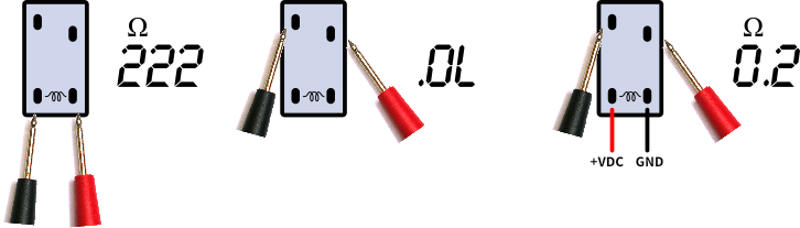
This four pin relay has a pair of pins equally spaced, which is the voltage and ground pins. These pins have a coil between them. Putting DC voltage across this will energise the coil and either connect or disconnect one or more pairs of switch pins to allow another circuit to flow.
- Measure the resistance across the voltage pins. The result is somewhere in the hundreds of Ohms.
- Measure the switch pins without any voltage across the voltage pins. In the case of a
Normally Openrelay, there should be no connection. - Measure the switch pins without voltage across the voltage pins. In the case of a
Normally Openrelay, there will be continuity.

In this five pin relay example, there is a pair of voltage pins, a common ground that then connects to both a Normally Open pin and a Normally Closed pin.
- Measure the resistance across the voltage pins. The result is somewhere in the hundreds of Ohms.
- Measure between
Common Groundand theNormally Openpins without any voltage across the voltage pins. There should be no connection. - Measure between
Common Groundand theNormally Closedpins without any voltage across the voltage pins. There should be continuity. - Measure between
Common Groundand theNormally Openpins with voltage across the voltage pins. There should be continuity. - Measure between
Common Groundand theNormally Closedpins with voltage across the voltage pins. There should be no connection.
A great fresher on many types of relays can be found here: What is relay
Transformers
Transformers are a whole can of worms (actually a can of iron and copper), so I won't go into great detail here. I'll just outline the regular steps you can take for sanity testing a transformer.
![]()
Identify which side is the primary and which side is the secondary. The primary side usually has two pins, though could still be more. Sometimes the primary wiring is thicker. Examine the terminals and connecting wire.
In the example above, the primary side is measuring 1 Ohm.
In the example above, the secondary has four pins.
The two outside pins usually represent the total resistance value on the secondary side, example: 4.7 Ohms.
Measuring an outside pin and one centre tap could represent a subset of the total. In our case 1 and 3 gives 2.7 Ohms. 3 and 4 gives 2.0 Ohms. 2.7 + 2.0 = 4.7.
In our example pin 2 is not connected, though a four pin secondary could easily have been configured as two secondary outputs.
![]()
- Ensure that there is no continuity/connection between any primary pin and any secondary pin. They should be physically isolated.
- No pins from either the primary or secondary should have continuity with the iron core.
- A power test can be performed by attaching AC power to the primary terminals and measuring the voltage across the secondary terminals, however, this is straying into dangerous territory and requires safety equipment. So I won't cover this technique in the cheatsheet. Points 1 to 3 should be enough to rule out the transformer.
To learn more about identifying the sides and wires of a transformer, I can recommend the these excellent videos:
Varistors
Ok, these suckers are tricky to test. They look like a capacitor, or a thermistor, but are nothing like them. Rather than try and explain how to tell them apart, you are better off using this excellent identification guide.
Varistors do not test like a resistor, so the resistance measurement will show no connection or continuity.
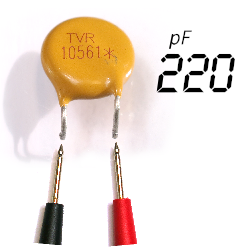
You can test them like a capacitor using a multimeter or GM-328. Don't expect a value that looks like something on the packaging. Just know if you get a low (pF) range value, you have some confidence that you have a working part. Again, check the guide above to get an appreciation of the expected values.
In my example is a TVR 10561. The 10 is component 10mm wide. The 561 is a 560V tolerant unit. If I mistook the 561 as a 561pF part, it will actually test at around 220pF mark which is roughly half, which lines up with the guide above.
Conclusion
This article is likely to expand over time. If this is handy for you, please pass it along to friends. I love to hear from other repairers, if you spot anything wrong, please let me know.