Table of Contents
ESP32 From Scratch
This guide will show you how to quickly set up an ESP32, placement onto a breadboard, wiring, the software, and finally sending code to it.
You will need an ESP32 Dev Board which you can purchase online from a variety of vendors. Prices can vary too. Mine was purchased from Aliexpress here: https://www.aliexpress.com/item/32928267626.html
Parts list:
- ESP32 Dev Board
- Breadboard (warning see below)
- Micro USB cable. The cable must be complete data and power cable, not just a charging cable.
Breadboards
Some versions the Dev Board are very wide and as a result, are too wide to fit within the central area of a breadboard. Only one side of the ESP32's pins will be accessible. Take this into consideration when purchasing. There are some good tips here: http://lucstechblog.blogspot.com/2018/08/breadboard-hack-for-esp32-and-esp8266.html
Software
Two software suites are available: either ExpressIf's own command line toolchain at: https://docs.espressif.com/projects/esp-idf/en/latest/esp32/get-started/windows-setup.html or you can use the Arduino IDE. Even though ESP32 is not an Arduino CPU, the IDE can support the ESP32. The Arduino IDE is a quicker and more visual way to program the ESP32. However, those more comfortable in the terminal might wish to try ExpressIf's software.
This guide will take you through the Arduino IDE.
Download and install using the instructions here: https://www.arduino.cc/en/Guide/Windows
Second, download the virtual COM port driver here: https://www.silabs.com/products/development-tools/software/usb-to-uart-bridge-vcp-drivers
For most regular Windows installs, choose Windows Universal download.
This driver will allow programming and serial communication from the Arduino IDE to the Dev Board via a COM port on your PC. Ensure the board is not plugged in when first installing the driver. Will make things less confusing for both you and your board.
Add the ESP32 support into the Arduino IDE using these instructions: https://docs.espressif.com/projects/arduino-esp32/en/latest/installing.html#installing-using-arduino-ide
Essentially, get the stable URL and add it to the “Additional Boards Manager URLs” under Preferences.
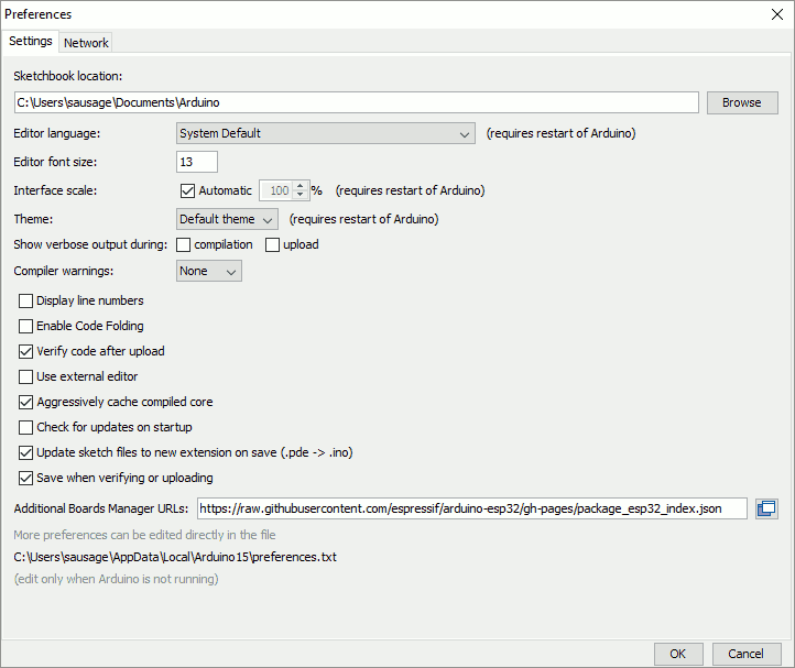
This will tell the Boards Manager how to find the library downloads for the ESP32 board.
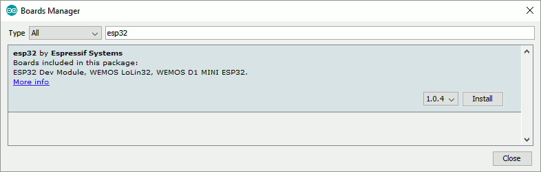
Go to the Boards Manager, filter by ESP32 and click Install:
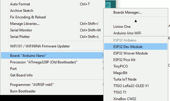
Finally, select the ESP32 as your current Dev board:
Hardware
Connect the ESP32 to a USB port on your computer. If you see the board being recognised, then you have a complete micro USB cable (not a charger only one, with data lines missing).
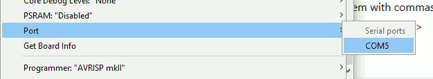
Check the device manager to see what Virtual COM port your PC has chosen:
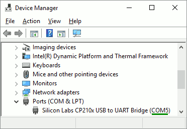
Set the Port in the Arduino IDE to the one noted in the Windows Device Manager.
Code
Your ESP32 is likely to have the onboard LED set off (not the power indicator LED). As a first simple program, we'll turn it on:
void setup() {
  // put your setup code here, to run once:
  pinMode(2, OUTPUT);
  digitalWrite(2, HIGH);
}

void loop() {
  // put your main code here, to run repeatedly:

}
Note above that we are setting pin 2 as an output pin and then writing the HIGH value to it, which means to supply voltage to the pin. The internal LED is tied to Pin 2 so it makes an excellent board verification indicator before connecting any electronics to the GPIO pins.
Verify and Compile.
If all succeeds, let's try sending the code to the ESP32.
Click Upload or press Control + U. Your program will recompile and try to upload to the board.
Typical output:
Serial port COM5
Connecting........_____....._____.....___

When you see the ''Connecting'' line above, press the ''BOOT'' button on the ESP32.

Chip is ESP32D0WDQ6 (revision 1)
Features: WiFi, BT, Dual Core, 240MHz, VRef calibration in efuse, Coding Scheme None
MAC: 24:6f:28:15:85:d8
Uploading stub...
Running stub...
Stub running...
...
...
Writing at 0x00001000... (100 %)
Wrote 17392 bytes (11186 compressed) at 0x00001000 in 0.1 seconds (effective 973.0 kbit/s)...
Hash of data verified.
Compressed 207632 bytes to 105298...

Writing at 0x00010000... (14 %)
...
Writing at 0x00024000... (85 %)
Writing at 0x00028000... (100 %)
Wrote 207632 bytes (105298 compressed) at 0x00010000 in 1.5 seconds (effective 1105.2 kbit/s)...
Hash of data verified.
Compressed 3072 bytes to 128...

Leaving...
Hard resetting via RTS pin...
At this point, you are done.
You can turn the LED off with:
void setup() {
  pinMode(2, OUTPUT);
  digitalWrite(2, LOW);
}

void loop() {
  // put your main code here, to run repeatedly:

}
Pinouts as reference
These are the pinouts to the board mentioned in this article (with micro USB located on the left):
VIN	GND	D13	D12	D14	D22	D26	D25	D33	D32	D35	D34	VN	VP	EN
 O	 O	 O	 O	 O	 O	 O	 O	 O	 O	 O	 O	 O	 O	 O

 O	 O	 O	 O	 O	 O	 O	 O	 O	 O	 O	 O	 O	 O	 O
3V3	GND	D15	D2	D4	RX2	TX2	D5	D18	D19	D21	RX0	TX0	D22	D23
There are many versions of the ESP32 and all pinouts vary.
References
http://lucstechblog.blogspot.com/2018/08/breadboard-hack-for-esp32-and-esp8266.html https://docs.platformio.org/en/latest/tutorials/espressif32/espidf_debugging_unit_testing_analysis.html#tutorial-espressif32-espidf-debugging-unit-testing-analysis https://www.youtube.com/watch?v=5edPOlQQKmo
Troubleshooting
serial.serialutil.SerialException: could not open port 'COM6': WindowsError(2, 'The system cannot find the file specified.')
Ensure you have the correct COM port set.
A fatal error occurred: Failed to connect to ESP32: Timed out waiting for packet header
Upload again and when you see Connecting…, hold down the “BOOT”/“FLASH” button. The flashing process will continue. If it does, release the BOOT/FLASH button
Upload again and when you see Connecting…, hold down the “BOOT”/“FLASH” button. Press the EN button once while continuing to hold “Boot/Flash”. The flashing process will continue. If it does, release both buttons.