Table of Contents
ESP32 OTA and Rollbacks - What happens under the hood?

Over The Air (OTA) provides a way to send firmware to your ESP32 board in the field without the need for a cable and physical access to the device.
The purpose of this article is to manually step through the various stages of the OTA process and illustrate the state of the ESP32 at each stage.
Together we will set up a number of firmwares suitable for testing on different partitions in flash memory.
OTA updates are often done via WIFI or Bluetooth, but we will be manually implementing each step (by hand) to fully appreciate what is going on under the hood.
Pre-requisites
It will be assumed that you have esp-idf installed and working, and that you know what your COM port number currently is. I'll use COM7 as an example throughout the article.
Your ESP32 board will need 4MB of flash memory.
It would be good for you to have read the general idea for how OTA and rollbacks work from the API Reference: https://docs.espressif.com/projects/esp-idf/en/latest/esp32/api-reference/system/ota.html
And in particular, please be familiar with the rollback process: https://docs.espressif.com/projects/esp-idf/en/latest/esp32/api-reference/system/ota.html#rollback-process
This article is based on esp-idf-v5.2.
The stock firmware
Let's assume that your ESP32 board is fresh out of the packet. It might have some demo firmware and partition information on it or, it might be completely blank. Let's take a look at what could be stored in the flash memory on the ESP32.
To read the current partition table out from the device (which lives at 0x8000) and dump it to a file:
esptool.py read_flash 0x8000 0xc00 partitions.log
Convert partition binary to readable CSV:
gen_esp32part.py .\partitions.log > .\partitions.csv
If you don't have gen_esp32part.py, please check the troubleshooter below.
Open the CSV, and it will probably look something like this (if anything at all):
# ESP-IDF Partition Table
# Name, Type, SubType, Offset, Size, Flags
nvs,data,nvs,0x9000,24K,
phy_init,data,phy,0xf000,4K,
factory,app,factory,0x10000,1M,
Ignoring the nvs and phy_init partitions, we have the default factory partition that starts at 0x10000. Ironically, the list of partitions doesn't list the bootloader partition at 0x1000 or the partition that the partition table itself is stored (at 0x8000).
OTA partitions
The factory partition is currently the only one here and this is where your firmware gets flashed to. We are going to add two extra partitions for OTA which can contain firmware as well.
Why are we adding OTA partitions?
Doing this will provide us with two slots where firmware can be uploaded to. If we upload the first, and the process fails, the ESP32 will rollback to factory as a failsafe.
If firmware is running on the first ota partition and a new firmware fails to upload to the second ota partition, the ESP32 will rollback to the first ota partition as a failsafe.
It's all about safely upgrading your device with your new software, and being able to keep going if there is a failure. This ensures you can try again another day.
Setting up an ESP32 project
In order that we can start doing some stuff together, let's make a new project.
idf.py create-project OtaProject
This gives us a project folder with a main subfolder containing our C file.
Head into the new project folder and set the projects build target to ESP32 or we won't get terribly far:
idf.py set-target esp32
We now have a build folder where our firmware will be built. Do a quick test build:
idf.py build
Setting up OTA partitions and ESP32 configuration
We will now set up the ESP32 to have OTA partitions. This can be done with the menuconfig.
idf.py menuconfig
Make your way to Partition Table > Partition Table (Single factory, no OTA).
Choose Factory app, two OTA definitions.
While here, we better ensure there is enough flash memory declared to hold all these partitions (they're 1MB a pop).
Serial Flasher config > Flash size > 4MB
And finally, as we will eventually be using the Rollback feature for when things go wrong:
Bootloader config > Enable app rollback support
Save and exit out. Build again with:
idf.py build
This will give you four binary images: the firmware, bootloader, otadata, and one for the partition table.
- partition-table.bin
- bootloader.bin
- OtaProject.bin
- ota_data_initial.bin
Now let's flash them all to the ESP32's flash memory.
idf.py -p COM7 flash
Inspecting the partitions in flash
Now let's download the partition setup again like we did before. This can be done with:
esptool.py read_flash 0x8000 0xc00 partitions.log
Convert partition binary to readable CSV:
gen_esp32part.py .\partitions.log > .\partitions.csv
We end up with a different partition table:
# ESP-IDF Partition Table
# Name, Type, SubType, Offset, Size, Flags
nvs,data,nvs,0x9000,16K,
otadata,data,ota,0xd000,8K,
phy_init,data,phy,0xf000,4K,
factory,app,factory,0x10000,1M,
ota_0,app,ota_0,0x110000,1M,
ota_1,app,ota_1,0x210000,1M,
ota_data_initial.bin is flashed to the otadata partition. OtaProject.bin is flashed to the factory partition. And nothing to the new ota_* partitions.
Preparing some test Firmware
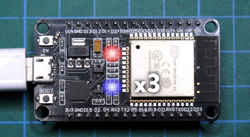
Let's make a simple firmware that blinks the onboard LED twice, then one that blinks three times and finally one that blinks four times.
They will be flashed to factory, ota_0 and ota_1 respectively.
Edit the main/OtaProject.c file and add the following:
#include "esp_log.h"
#include "driver/gpio.h"
#include "freertos/FreeRTOS.h"
#include "freertos/task.h"

#define BUILT_IN_LED    2
#define ON              1
#define OFF             0
#define BLINKS          2

void app_main(void)
{
    gpio_set_direction(BUILT_IN_LED, GPIO_MODE_OUTPUT);

    ESP_LOGI("APP", "Flash LED.");

    while(1){

        int i;
        for (i=0; i<BLINKS; i++){
            gpio_set_level(BUILT_IN_LED, ON);
            vTaskDelay(25);
            gpio_set_level(BUILT_IN_LED, OFF);
            vTaskDelay(25);
        }

        gpio_set_level(BUILT_IN_LED, OFF);
        vTaskDelay(200);
   }

}
Build the new code with:
idf.py build
And flash the double blink firmware to the factory partition with:
idf.py -p COM7 flash
And we get the LED blinking twice.
We'll keep a copy of each firmware. Rename build/OtaProject.bin to build/2blinks.bin.
Make a three blink firmware by changing the define in our program to:
#define BLINKS 3
Rebuild with:
idf.py build
Rename build/OtaProject.bin to build/3blinks.bin.
Do the same again to make a four blink version.
We should have three firmware files:
- 2blinks.bin
- 3blinks.bin
- 4blinks.bin
Note that the idf.py flash command is only able to flash the default project firmware to the factory partition. So we'll need to switch to a different command to flash a named firmware to a particular partition.
Take another look at our partitions table.
# ESP-IDF Partition Table
# Name, Type, SubType, Offset, Size, Flags
nvs,data,nvs,0x9000,16K,
otadata,data,ota,0xd000,8K,
phy_init,data,phy,0xf000,4K,
factory,app,factory,0x10000,1M,
ota_0,app,ota_0,0x110000,1M,
ota_1,app,ota_1,0x210000,1M,
- factory is located at 0x10000
- ota_0 is located at 0x110000
- ota_1 is located at 0x210000
Let's test each firmware by flashing them to the factory partition.
esptool.py -p COM7 write_flash 0x10000 .\build\3blinks.bin
esptool.py -p COM7 write_flash 0x10000 .\build\4blinks.bin

And put the 2blinks version back onto factory with:
esptool.py -p COM7 write_flash 0x10000 .\build\2blinks.bin
And let's flash 3blinks onto ota_0 and 4blinks onto ota_1. We could use the esptool.py for this, but we'll use the otatool.py tool because you don't need to know the address of the partition. You can use the partition name instead.
otatool.py -p COM7 write_ota_partition --name=ota_0 --input=.\build\3blinks.bin
After uploading, the ESP32 resets but the 2blinks firmware still operates from the factory partition. All well so far. Now for 4blinks to ota_1:
otatool.py -p COM7 write_ota_partition --name=ota_1 --input=.\build\4blinks.bin
Again, 2blinks firmware still operates from the factory partition.
Switching firmware, and the otadata partition
Check the partition table again.
# ESP-IDF Partition Table
# Name, Type, SubType, Offset, Size, Flags
nvs,data,nvs,0x9000,16K,
otadata,data,ota,0xd000,8K,
phy_init,data,phy,0xf000,4K,
factory,app,factory,0x10000,1M,
ota_0,app,ota_0,0x110000,1M,
ota_1,app,ota_1,0x210000,1M,
Notice the otadata partition. The bootloader uses this to choose which partition's firmware to boot: factory, ota_0 or ota_1.
At the moment, the otadata partition is filled with 0xFF bytes. Because of this, the bootloader will choose the firmware on the factory partition.
Let's prove that otadata contains nothing but 0xFF bytes.
esptool.py read_flash 0xD000 0x2000 otadata-partition.bin
This reads out the otadata partition, which starts at 0xd000 and is 0x2000 in length out to a file.
If you open the otadata-partition.bin file in a hex reader (I recommend HxD), you'll see that the entire file is filled with 0xFF bytes.
We can use a tool to set ota_0s firmware as the one we want to boot from:
otatool.py -p COM7 switch_ota_partition --name=ota_0
The device will reset and notice that there are three LED blinks. This is the 3blinks firmware running on ota_0.
Let's get a summary from the current otadata partition:
otatool.py --port COM7 read_otadata
             OTA_SEQ      CRC      |      OTA_SEQ          CRC
Firmware:  0x00000001   0x4743989a |    0xffffffff       0xffffffff
Interesting. On the left is ota_0. It has a boot sequence of 01 and a CRC checksum (keep a note of this, we will come back to this). This partition will boot each time the ESP32 is reset. On the right is ota_1, and there is nothing here to indicate if it should boot.
We can also verify the otadata partition and take a closer look at what is stored there now.
esptool.py read_flash 0xD000 0x2000 otadata-partition.bin
Looking at the file in our hex editor, we discover the same raw data:
01 00 00 00 FF FF FF FF FF FF FF FF FF FF FF FF
FF FF FF FF FF FF FF FF FF FF FF FF 9A 98 43 47
The first four bytes are the boot sequence. It's little-endian so this is sequence 01. There is nothing else in the sequence, so this firmware wins.
9A 98 43 47 is the firmware checksum.
Remember the CRC checksum in ota_0?
0x4743989a. This is how you can confirm which firmware is running.
Let's switch to booting the firmware on ota_1:
otatool.py -p COM7 switch_ota_partition --name=ota_1
The ESP32 will reboot and the LED will begin blinking 4 times. This is the 4blinks firmware booted on the ota_1 partition.
Take a look at the otadata information again:
otatool.py --port COM7 read_otadata
             OTA_SEQ      CRC      |      OTA_SEQ          CRC
Firmware:  0x00000001   0x4743989a |    0x00000002       0x55f63774
Hello, what have we here? There is an 02 sequence on the ota_1 side. This is higher than the 01 sequence, so ota_1 wins.
But we should also take a closer look at the raw contents of the otadata partition:
esptool.py read_flash 0xD000 0x2000 otadata-partition.bin
The file should update in our hex editor. If not, reload it:
00000000 	01 00 00 00 FF FF FF FF FF FF FF FF FF FF FF FF
		FF FF FF FF FF FF FF FF FF FF FF FF 9A 98 43 47

...

00001000	02 00 00 00 FF FF FF FF FF FF FF FF FF FF FF FF
		FF FF FF FF FF FF FF FF FF FF FF FF 74 37 F6 55
At the top of the file is the 01 sequence we saw earlier. But now, there is a new entry at 0x00001000. This is the second flash sector. The otadata partition has two sectors 0x1000 in size each. This is a safety feature. If one sector is damaged during an update to the otadata, the data in the other sector can be retrieved.
In our case, the second sector has a new entry, the 02 sequence. This is for the firmware on ota_1. 02 is greater than 01 so this is the firmware selected for boot by the bootloader.
Again we can inspect the checksum: 0x55f63774 is 74 37 F6 55.
How an OTA partition is determined from sequence numbers in the otadata partition is not explained in the documentation, but is explained in the code. You can see it here: https://github.com/pycom/esp-idf-2.0/blob/master/components/app_update/esp_ota_ops.c#L297
Essentially, for two partitions all odd sequence numbers are ota_0 and even numbers are ota_1. The formula is:
(ota_seq - 1) % number_of_ota_partitions
Revise on the otadata partition here:
https://docs.espressif.com/projects/esp-idf/en/latest/esp32/api-reference/system/ota.html#ota-data-partition
Simulating Rollback process
During a real OTA update where a firmware is sent to the ESP32 over Wifi or Bluetooth, the firmware running on the ESP32 is responsible for setting the otadata flash sector with the status of ESP_OTA_IMG_NEW for that OTA partition.
In our case, using the otatool.py switch_ota_partition tool/command to switch firmwares does not set a status at all. There appears to be no tool under the esp-idf that is capable of doing this. Instead, we can simulate these status changes to the otadata by editing the otadata-partition.bin file, and then reflashing it to the ESP32.
In the otadata-partition.bin, I have indicated the position of the status with XX XX XX XX:
00001000	02 00 00 00 FF FF FF FF FF FF FF FF FF FF FF FF
		FF FF FF FF FF FF FF FF XX XX XX XX 74 37 F6 55
You can find the enum for the statuses here:
The value for ESP_OTA_IMG_NEW = 0x0U. Therefore, edit the bin file to become:
00001000	02 00 00 00 FF FF FF FF FF FF FF FF FF FF FF FF
		FF FF FF FF FF FF FF FF 00 00 00 00 74 37 F6 55
Save the file and reflash it over the top of the existing otadata partition:
esptool.py -p COM7 write_flash 0xd000 .\otadata-partition.bin
The device will reset and the 4blinks firmware is still running on the ESP32 from the otadata partition.
Let's extract the otadata partition again, and inspect if it changed again:
esptool.py read_flash 0xD000 0x2000 otadata-partition.bin
00001000	02 00 00 00 FF FF FF FF FF FF FF FF FF FF FF FF
		FF FF FF FF FF FF FF FF 01 00 00 00 74 37 F6 55
Remember this is in the second flash sector at 0x1000 so you might have to scroll down in your hex editor. Notice the interesting change. 00 00 00 00 has become 01 00 00 00.
The status of the firmware on ota_1 is 01 which is: ESP_OTA_IMG_PENDING_VERIFY.
Why is it pending a verify? Let's refresh our memory on the states here: https://docs.espressif.com/projects/esp-idf/en/release-v3.3/api-reference/system/ota.html#app-ota-state
We enabled CONFIG_APP_ROLLBACK_ENABLE in our config, but we never used esp_ota_mark_app_valid_cancel_rollback() in our firmware code. Therefore the firmware will execute but on the next reboot and execution, our esp_ota_mark_app_valid_cancel_rollback() will still be missing. I predict our partition is going to be marked as aborted.
Let's see. All we need to do is to reset the ESP32. Press the reset button.
Wow, notice something? The 3blinks firmware from ota_0 has been booted. Let's extract the otadata again and take a look what has occurred:
esptool.py read_flash 0xD000 0x2000 otadata-partition.bin
00000000 	01 00 00 00 FF FF FF FF FF FF FF FF FF FF FF FF
		FF FF FF FF FF FF FF FF FF FF FF FF 9A 98 43 47

...

00001000	02 00 00 00 FF FF FF FF FF FF FF FF FF FF FF FF
		FF FF FF FF FF FF FF FF 04 00 00 00 74 37 F6 55
Ok so the status on the ota_1 firmware is now 04. What does this mean? Yep: ESP_OTA_IMG_ABORTED. So there is a new situation in otadata. The 02 sequence is greater than the 01, but 02 has an aborted state. So 01 on ota_0 wins. And that contains our 3blinks firmware and is the reason why the ota_0 has booted.
Let's now set the status on the 01 sequence in the first flash sector as ESP_OTA_IMG_NEW in the hex editor:
00000000 	01 00 00 00 FF FF FF FF FF FF FF FF FF FF FF FF
		FF FF FF FF FF FF FF FF 00 00 00 00 9A 98 43 47
Save and reflash the file to the otadata partition:
esptool.py -p COM7 write_flash 0xd000 .\otadata-partition.bin
The ESP32 will reset and 3blinks firmware continues to execute. Let's take a look at the raw otadata again:
esptool.py read_flash 0xD000 0x2000 otadata-partition.bin
00000000 	01 00 00 00 FF FF FF FF FF FF FF FF FF FF FF FF
		FF FF FF FF FF FF FF FF 01 00 00 00 9A 98 43 47
As before, the status has moved to 01, ESP_OTA_IMG_PENDING_VERIFY.
Press the reset button on the ESP32. I wonder what will happen?
Yes, the ESP32's LED will be blinking twice. This is the 2blinks firmware. And where is it running? Yep back on the factory partition. Pretty amazing isn't it?
All our firmwares failed to run the esp_ota_mark_app_valid_cancel_rollback() to mark the otadata as valid. So in each case, they have become aborted and rolled back to the previously known good firmware.
The factory firmware isn't affected by otadata, or the rollback process, or OTA at all.
To finish up, let's take a last look at the raw otadata:
esptool.py read_flash 0xD000 0x2000 otadata-partition.bin
00000000 	01 00 00 00 FF FF FF FF FF FF FF FF FF FF FF FF
		FF FF FF FF FF FF FF FF 04 00 00 00 9A 98 43 47

...

00001000	02 00 00 00 FF FF FF FF FF FF FF FF FF FF FF FF
		FF FF FF FF FF FF FF FF 04 00 00 00 74 37 F6 55
Sure enough both flash sectors have aborted entries. You can reset back to factory by wiping the otadata partition. We're already running there, but if you want to clean up and start over:
otatool.py --port COM7 erase_otadata
That's it for now. I hope this helps you understand what OTA is doing under the hood, why a status needs to be set for a firmware, and how we can ensure that our firmware partition needs to be set as valid during it's startup.
Have fun!
Troubleshooting
The gen_esp32part.py command isn't found.
For some reason, gen_esp32part.py is not added to your path by default when starting your ESP-IDF console. For Powershell add the following to line 59 of your frameworks\esp-idf-v5.2\export.ps1 file:
function gen_esp32part.py { &python "$IDF_PATH\components\partition_table\gen_esp32part.py" $args }
For Windows Command Prompt, in frameworks\esp-idf-v5.2\export.bat add to line 66:
DOSKEY gen_esp32part.py=python.exe "%IDF_PATH%\components\partition_table\gen_esp32part.py" $*
For shell and fish terminals, it's the same deal.
More reading
Thank yous
Many thanks to boarchuz and craig from the Espressif MCUs discord server for their assistance with this article.