Table of Contents
ESP32-S2 and the APA102 RGB LED
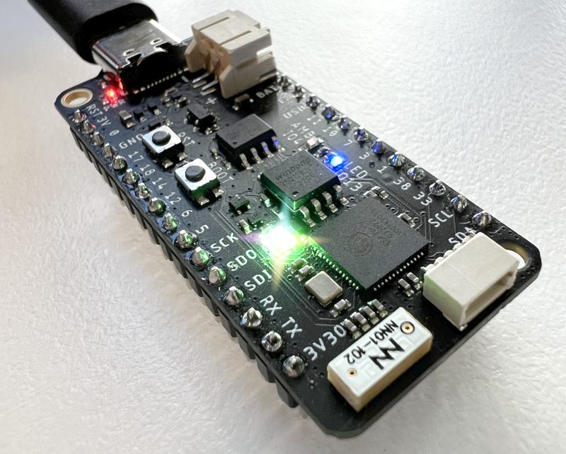
I recently picked up the UnexpectedMaker FeatherS2 which is an ESP32-S2 based board in a feather form-factor.
It's a really nicely produced board from an Australian Indie hardware manufacturer.
Of course, when you receive a new board, the first thing you're going to want to do is flash the LED, right? It's in the constitution. And this one has an RGB LED. Sweet, three signals to the LED. That won't be hard.
But wait up, this is an APA102 RGB LED. It has data and clock pins.
So I jumped onto both the UnexpectedMaker and FeatherS2 sites. Surprisingly and there is little guidance to using it, you're pretty much on your own. Thankfully there is a regular onboard blue LED provided for standard blinky. But we all want the colours right?
Pre-requisites
For this article it will be assumed that you have esp-idf installed and working, and that you know what your COM port number currently is. I'll use COM7 as an example throughout the article.
An ESP32-S2 based board with an APA102 RGB LED or SK9822 LED.
You should be able to follow along with an equivalent ESP32-S2 board.
This article is based on esp-idf-v5.2
Setting up an ESP32-S2 project
In order that we can get the RGB LED working together, let's make a new project.
idf.py create-project apa-102
This gives us a project folder with a main subfolder containing our C file.
Head into the new project folder and set the projects build to target our board type or we won't get terribly far:
idf.py set-target esp32s2
We now have a build folder where our firmware will be built.
We to make a change in our menuconfig to ensure we can get debug information through USB:
idf.py menuconfig
Set: Component config > ESP System Settings > Channel for console output > USB CDC
Do a quick test build:
idf.py build
The datasheet
Time to dig up a datasheet. Thankfully they are available all over the place, like this one from Components 101.
Looking at the sheet, this is an addressable RGB LED. It can be daisy chained with more LEDs. So these are pretty much what you get in those light strips that our kids bug us to install into their bedrooms so they can burn out their retinas.
The device communicates over a serial interface. So we'll be using SPI.
In order to set a colour, we send a carefully crafted sequence of bytes. More on that soon.
The initialisation code
Open main/apa-102.c and start with:
#include <stdio.h>

void initApa102(){}

void setRGBToYellow(){}

void app_main(void)
{
    initApa102();
    setRGBToYellow();
}
Of course this does nothing but it will show the bones of all that needs to occur in order to set the colour of the LED. First, the APA102 will need to be initialised. This means setting it up for serial communication.
The second step is to send a sequence of bytes to change the colour. There does not need to be a loop to maintain the colour or any continued communication. Once the byte sequence is sent to the LED, it will remain that colour until it receives new information.
Test compile your code with:
idf.py build
For the initApa102 function, we bring in some includes and set the code as:
#include <stdio.h>
#include <string.h>
#include "driver/spi_master.h"
#include "hal/spi_types.h"
#include "esp_log.h"
#include "driver/gpio.h"

spi_device_handle_t spi;
#define RGB_CLK_PIN 45
#define RGB_DATA_PIN 40
#define ENABLE_RGB_POWER_PIN  21 //RGB LED not usable unless 21 is active.

void initApa102(){
    spi_device_interface_config_t devcfg = {
        .clock_speed_hz = 10000,   // Clock out at 10 kHz
        .queue_size = 1            // Queue 1 transaction at a time
    };

    spi_bus_config_t buscfg = {
        .mosi_io_num = RGB_DATA,
        .sclk_io_num = RGB_CLK,
    };

    // Initialize the SPI
    spi_bus_initialize(FSPI_HOST, &buscfg, 1);

    // Define SPI handle
    spi_bus_add_device(FSPI_HOST, &devcfg, &spi);

    //Supply power to the RGB
    gpio_set_direction(ENABLE_RGB_POWER_PIN, GPIO_MODE_OUTPUT);
    gpio_set_level(ENABLE_RGB_POWER_PIN, 1);
}

void setRGBToYellow(){}

void app_main(void)
{
    initApa102();
    setRGBToYellow();
}
To explain the initApa102 function, we have a minimal SPI Interface Config and a minimal SPI Bus Config. These configs are set to a SPI host device it is for.
Our host is FSPI_HOST. This is one that is controlling the LED. On ESP32 boards (non S2), this SPI is named HSPI_HOST.
Pin 21 needs to be turned on to supply the power to the APA102.
Setting the LED colour
Back to the datasheet you can see that a sequence of 12 bytes (96 bits) is defined.

The first frame is 4 bytes, each 0x00.
The LED frame is 3 blank bits, 5 bits to represent brightness, then one byte for blue, one byte for green and one byte for red.
The last frame is 4 bytes, each 0xFF.
Pretty straight forward really.
Implement the setRGBToYellow function as:
void setRGBToYellow(){
    uint8_t red   = 0xFF;
    uint8_t green = 0xFF;
    uint8_t blue  = 0x00;

    uint8_t rgbBits[] = {
        //Start Frame
        0x00, 0x00, 0x00, 0x00,

        //LED Frame
        0b11100111, //3 bits //5 bits brightness
        blue,
        green,
        red,

        //End Frame
        0xFF, 0xFF, 0xFF, 0xFF
    };

    spi_transaction_t trans;
    memset(&trans, 0, sizeof(trans));

    trans.length = 96;              // length of rgbBits array in bits
    trans.tx_buffer = rgbBits;

    spi_device_transmit(spi, &trans);
}
Start by setting the three colour bytes. You can change these values to experiment with all sorts of colours.
Next is construction of the rgbBits array. Using the datasheet, I've built the data sequence using a mixture of binary and hex notation to make it easy to compare against what the datasheet suggests.
Then add the array to a SPI transaction and transmit to the APA102 SPI device.
The APA102 will respond to this data by lighting up!
Where to from here?
You can achieve a number of effects, colour combinations and brightness levels. Feel free to check out my APA102 fader code at: https://github.com/sausagejohnson/apa102-fader-serial/blob/master/main/main.c
The code takes two colours and smoothly fades back and forth between the two using a FreeRTOS task. This is easy to implement into a small library for your own projects.
Troubleshooting
The LED won't come on? There are a number of things to re-check:
- Firmware may have crashed. Ensure USB CDC is set in the menuconfig.
- Ensure RGB_DATA_PIN is set to mosi_io_num and RGB_CLK_PIN to sclk_io_num. Check it's not the wrong way around.
- Ensure pin 21 is on to supply power.
- FSPI_HOST must be chosen host.
- The byte sequence sent to the APA102 must be correct.