Table of Contents
Open Source FPGA toolchain on The Go Board
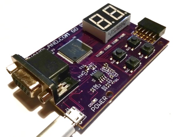 The Go Board is an excellent FPGA dev board that contains four switches, four LEDs, two 7-segments, a PMOD, and a VGA connector.
I love it for sketching out quick ideas and experiments.
For details on buying one, plus all the documentation and video tutorials, head to: nandland.com
Most of the material there focuses on the commercial iCEcube2 and Lattice Diamond tools. There is one video that largely outlines the use of the open source tools, but this is from a few years ago.
This article aims to take you through a more recent version of yosys, nextpnr, and the Icestorm tools on Windows specifically.
There will also be tips along the way and some troubleshooting at the end for when you don't always get the happy path.
Getting the tools
There are various ways to get the tools. But for Windows, it's not so straight forward. My current pick is still downloading from: https://github.com/im-tomu/fomu.im/releases/download/td19/yosys-icestorm-nextpnr-win64.0.1.zip
This is one version back from the latest, but it will suit fine.
The Hardware
The Go Board contains the iCE40HX1K FPGA in a VQ100 package. We need this information for later.
The board operates at 25MHz.
Setting up a project
This will be pleasantly simple.
Just create a project folder:
blinky-from-scratch
Constraints
A constraint is what maps a pin to a name.
The open source tools use the PCF file format (Physical Constraints File) just as the commercial iCEcube2 application does.
Create the constraints file which maps the code names to the individual input and output pins of the FPGA called board-constraints.pcf:
set_io i_Clk 15
set_io o_LED_2 57
We are only interested in the clock-in and the pin that goes to the second LED (I picked that at random). That's all that will be in the constraints file.
There is no harm in supplying the full constraints file if you prefer. You'll just see some “Warning: unmatched constraint” messages during the place and route step.
The FPGA Code
Create a blink.v verilog file which will contain simple clock divider routine and change a reg bit after each threshold of clock pulses. And then change the state of an LED on the Go Board.
module blink
    (
        input i_Clk,
        output o_LED_2
    );

    localparam integer slowDownClkThreshhold = 5000000;
    reg [31:0] thresholdCounter = 0;

    reg r_LED = 1'b0;

    always @(posedge i_Clk)
        begin
            if (thresholdCounter > slowDownClkThreshhold)
                begin
                    r_LED <= !r_LED;
                    thresholdCounter <= 0;
                end
            else
                begin
                    thresholdCounter <= thresholdCounter + 1;
                end
        end

    assign o_LED_2 = r_LED;

endmodule
The FPGA Tools
iverilog is a great tool for doing a quick synthesis and checking that there are no issues with the code.
iverilog blink.v
Once happy with the code, then we can move onto the actual synthesis using yosys.
Type: yosys and press enter.
Execute the following commands at the yosys prompt:
read_verilog blink.v
synth_ice40
write_json design.json
The above three commands will read in the blink.v verilog file, synthesise the code for an Ice40, then output the design as a JSON file.
The following command runs the place and route for the Ice40 FPGA used on the Go Board. It sets the dev board's clock to 25MHz, uses the stripped down constraints file to map the pins, takes in the synthesised design JSON file from yosys, sets the package type and finally outputs the bitstream in ascii/txt format.
nextpnr-ice40.exe --hx1k --freq 25 --pcf board-constraints.pcf --json design.json --package vq100 --asc bitstream.txt
The resulting bitstream.txt file cannot be used to send to the FPGA. It needs to be packed into a binary first:
icepack bitstream.txt bitstream.bin
The correct USB Drivers
This document does not go into detail about the installation of the Virtual COM Port driver. I am assuming that the reader has these already.
But the point is that these drivers are only good for using the commercial tools. The open source tools require changing the drivers to the libusbK ones. Some details on how to convert the driver is here: https://github.com/joshajohnson/WTFpga/blob/a0347ae5b7c024e8f1ba95e6a5287bc7eb07af86/install.md#windows-installation
Note: if you switch to libusbK, you cannot use the commercial tools like Lattice Diamond.
Programming the Go Board
Here is the simple part. Simply enter:
iceprog bitstream.bin
You will get the following output:
init..
cdone: high
reset..
cdone: low
flash ID: 0x20 0x20 0x11 0x00
file size: 32220
erase 64kB sector at 0x000000..
programming..
reading..
VERIFY OK
cdone: high
Bye.
Within a few seconds your Go Board will be executing your code. You are done. Congratulations on a successful open source toolchain for your Go Board.
Extra Notes
For yosys you can script the various commands that we entered earlier to help partially automate your workflow.
For the constaints file, you can supply the entire set of constraints, but you will receive harmless warnings. If you would like to supress the warnings, add the -nowarn flag to each entry in the PCF file like this:
set_io -nowarn o_LED_2 57
Troubleshooting
When using iceprog if you get a message:
Can't find iCE FTDI USB device (vendor_id 0x0403, device_id 0x6010 or 0x6014).
ABORT.
This means you are using the standard USB COM port drivers. You need to change them to libusbK. See the following on how to use zadig to change them: https://learn.adafruit.com/adafruit-ft232h-breakout/windows-setup or https://gojimmypi.blogspot.com/2020/12/ice40-fpga-programming-with-wsl-and.html
When using iceprog if you get a message:
Found difference between flash and file!
It is probable that you are trying to iceprog a bitstream that is not packed into a binary format yet. Check the icepack step in this article.
When using nextpnr you get a warning message in the output that says:
Warning: No clocks found in design
Could be a variety of reasons, and nothing to do with having no clock in your design. You probably do have one. The main reason could be the incorrect declaration and use of a reg. Check you are not using a 1-bit instead of a 32bit reg.