This is an old revision of the document!
Table of Contents
Oscillators on the PIC16F1455
Oscillators on a PIC can be a bit of a minefield to understand. Especially learning to read through a datasheet. There are internal and external oscillators (many external options), PLLs, low frequencies and high frequencies. So it can be a little daunting just to get a baseline start.
Even checking the datasheet to see what the default internal oscillator clock frequency is, is not 100% clear.
Hopefully I can help here.
So let's start out.
I'll cut straight to the answer; the default clock frequency on the PIC16F1455 is 500kHz. This frequency comes from the High Frequency Internal Oscillator or (HFINTOSC). There is no PLL no achieve this frequency (more on this later).
Page 73 of the datasheet tells us that 500kHz is the “default upon Reset”. So that is the default power-on frequency of the PIC16F1455.
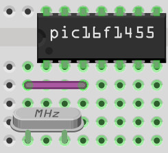
If you need a basic breadboard wiring diagram for the PIC16F1455, you can check the previous article.
Setting a different frequency
So what about setting up a different frequency? Let's go for 62.5kHz
While you can probably do this in a couple of steps, let's go over them all to have a better appreciation of how to set up the oscillator on this PIC.
Using the internal oscillator
Rather than use an external oscillator, use the internal one. There are two way to do this. You can either declare this at the top of your code with:
#pragma config FOSC = INTOSC // INTOSC = Internal Oscillator
The other way is to write into the SCS bits of the OSCCON register at the top of your main() function:
OSCCONbits.SCS = 0b11; //or 0b10, only the second bit is meaningful
Choosing the frequency
Here's the actual part you're probably interested in, how to choose the frequency. This is set using the four IRCF bits of the OSCCON register. Again, page 73 of the datasheet lists all the frequencies. 62.5kHz is listed as: 0100. Therefore, set the bits with:
OSCCONbits.IRCF = 0b0100; //62.5kHz
Setting to the internal oscillator (default anyway), and selecting your frequency with IRCF is the simplest way to choose your frequency.
The delay function
The PIC headers supply a neat function called __delay_ms(). This allows you to pause for an amount of milliseconds before moving on the next line of code.
This is very handy for performing a task like turning on an LED, pausing, and turning off the LED or some other signal. Unfortunately, we need supply a define for this function to calculate time correctly. In our case, we have set the clock frequency to 62.5kHz which is 62500Hz. So we need to supply the define as:
#define _XTAL_FREQ 62500 //clock delay timing as 62.5kHz
Now the __delay_ms() function will be accurate when we use it. It's a pity that it isn't possible for the function to determine this frequency from our configuration bits or code, but that's life.
Now if we add a while loop to turn on and off an LED connected to RC2:
    while (1){
	LATC2 = 1;
	__delay_ms(1000);
	LATC2 = 0;
	__delay_ms(1000);
    }
The on and off will be accurately changing every second, thanks to ensuring that _XTAL_FREQ matches the frequency chosen with the IRCF bits in the OSCCON register.
Using PLL to achieve 24MHz
The PIC16F1455's internal oscillator is 16MHz. The PLL enables clock speeds above 16MHz, namely: 24MHz, 32MHz and 48MHz.
The rules for getting the PLL mode to be accepted are a little funny. When choosing the internal oscillator, for PLL frequencies you HAVE to turn off the SCS bits in the OSCCON register with:
OSCCONbits.SCS = 0b00; //want the FOSC configuration bits to choose internal or external oscillator
And then set to internal oscillator with the following configuration bits:
#pragma config FOSC = INTOSC // INTOSC = Internal Oscillator
(Section 5.2.2.5 of the datasheet spells this out)
The PLL frequencies need to start with the 8kHZ frequency as a baseline:
OSCCONbits.IRCF = 0b1110; //8MHz base
Now that the base frequency is set to 8MHz, set the SPLLMULT bit of the OSCCON register to 1. This means to switch to 3X PLL (or 8MHz * 3 = 24MHz):
OSCCONbits.SPLLMULT = 1;
Enable the PLL by setting the SPLLEN (PLL enable) with:
OSCCONbits.SPLLEN = 1;
Set the _XTAL_FREQ to 24MHz with:
#define _XTAL_FREQ 24000000UL //24MHz
Now there is one last thing to do, and this is not covered by the datasheet: the CPUDIV configuration word will trip you up. CPUDIV needs to be set to NOCLKDIV with:
#pragma config CPUDIV = NOCLKDIV
If you didn't do the CLKDIV, the PLL would not be active and the oscillator would be set to 8MHz only. And with an _XTAL_FREQ of 24,000,000, your LED blinking would end up 3 times slower due to __delay_ms() using bad maths.
The datasheet does not list what the default for clock division is when resetting a PIC. However, the default in the configuration bits is shown as: CLKDIV6 (using the MPLAB X IDE). Which means to divide the CPU clock by six. Or… make the CPU a sixth the normal speed.
Low Frequency Internal Oscillator (LFINTOSC)
On page 73 of the datasheet lists all the internal frequencies that are available. The last one is the 31kHz speed which is the only low frequency available. You can select this frequency by setting all the IRCF bits in the OSCCON register to 0000:
OSCCONbits.IRCF = 0b0000; //31kHz
The PLL will have no effect on this frequency. But best to remove any PLL setup from your code.
Be sure to match _XTAL_FREQ for the __delay_ms() function by setting:
#define _XTAL_FREQ 31000 //31kHz
That covers a few of the internal oscillator frequency choices, with and without PLL. Now for an external oscillator.
External Oscillators
So why an external oscillator? What's wrong with the internal one? In a word it comes down to accuracy. An external oscillator can offer great accuracy over long time spans. It depends on your application if this is crucial for your project or not.
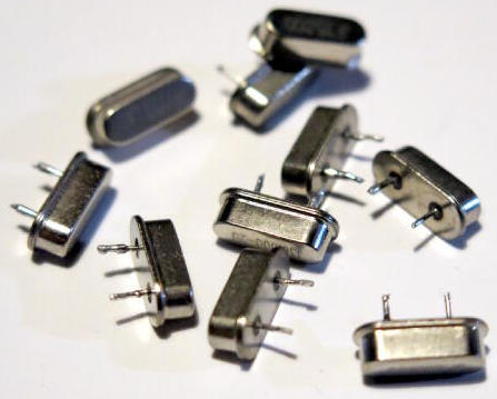
There are many oscillator choices here. But we will cover using a crystal.
A crystal for a PIC16F1455 is connected between pins OSC1 and OSC2.
Crystals should be hooked up using a resister and capacitors as per the datasheet on page 58. But for the sake of simplicity I'll add a 17.664MHz crystal directly to pins 2 (OSC1) and 3 (OSC2).
The signal will be a little rougher without the capacitors and grounding, and be subject to interference. But this will work fine for testing.
I've chosen 17.664MHz because it is between the required 4MHz and 20MHz range, and it is an unusual frequency. Which makes it perfect to demonstrate.
On page 55 of the datasheet is a good write up of the various oscillator modes. I've chosen the HS mode. Therefore we can tell the PIC that we want to use an external oscillator and we want the HS mode:
#pragma config FOSC = HS
Set the _XTAL_FREQ for the __delay_ms() function for 17.664MHz:
#define _XTAL_FREQ 17664000UL //17.664MHz
And finally, the only OSCCON register setting you need is:
OSCCONbits.SCS = 0b00;
Which ensures that the FOSC setting is taken from the FOSC configuration bits.
Double check that you still have no CLKDIV:
#pragma config CPUDIV = NOCLKDIV
And now you have the LED blinking on/off once per second using an external oscillator.
Conclusion
Hopefully that should help you get some confidence with using oscillators on the PIC16F1455, and how to change the various settings of the PIC to choose the frequency you want, whether internal or external. Remember that there are some sneaky things that are often overlooked that affect your timing loops and delays like the _XTAL_FREQ. Also the CLKDIV configuration bits, which can also affect your timing, but moreso, can affect the working of the PLL.
Excellent resource: https://www.rakeshmondal.info/Blink-led-xc8-pic18F4550-20MHz-external