Table of Contents
Using GPIO RA3 on a PIC16F1455
The PIC16F1455 is only a small microcontroller with 14 pins. The datasheet does claim up to 14 I/O pins, but practically RA0, RA1, RA3, RA4 and RA5 are available on PORT A, and RC0, RC1, RC2, RC3, RC4 and RC5 are available on PORT C. And that's it. There is no PORT B.

That gives 11 GPIO. That's some good loot. But there are limitations. RA0, RA1 and RA3 are input only. That's fine - they can be the first choice for any pull-up resistors acting as input switches.
As you start to allocate out and plan what functions the pins will perform in your design, the choices start to thin out quickly. Some GPIO pins share with other functionality.
For example, the RA3 pin is also the MCLR pin which is very important for controlling the resetting during the ICSP programming. And RC0 and RC1 are the ICSPDAT and ICSPCLK pins used for the actual programming.
Eventually you need to double up on a pin to try and get the value from both features.
For this article, I'll be picking on RA3.
RA3
RA3 shares GPIO with MCLR. If you are wanting to use the input-only RA3 for a switch, you are still going to need the pin for programming further software changes as you develop your solution.
Low Voltage programming (LVP) is often quoted as one solution to the problem (moving to using pins 12 and 13 for programming), but getting that to work can be more trouble that it is worth.
Thankfully it is possible to stick with high voltage programming, which I'd warrant the average punter would be more comfortable with.
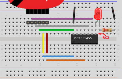
This is a simple and standard way to wire up a PIC16F1455 as outlined in: Minimum setup for a PIC16F1455 on a Breadboard + PICkit3.
Here is a similar layout, but with a switch and pull-up resistor added onto an easier pin: RC3.
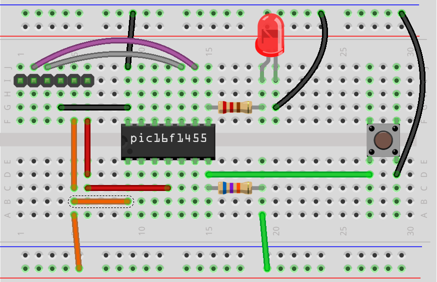
As a reminder for inputs: 5V must be held on the pin to indicate NO input. The pull-up resistor will greatly reduce the wasted current used on the pin. Secondly, using a switch to ground the pin indicates input.
Seems anti-intuitive, but that's how it works.
Disabling MCLR
If RA3 was the desired input pin to use, MCLR would need to be disabled. This is possible with the following two configuration bits:
#pragma config MCLRE = OFF      // MCLR Pin Function disable (MCLR/VPP pin function becomes digital input)
#pragma config LVP = OFF        // Low-Voltage Programming Disable (High-voltage programming enabled)
This can be verified at Register 4-1 of the datasheet:

This confirms that if MCLR is disabled, and LVR is disabled, RA3 will act as a normal digital input-only pin.
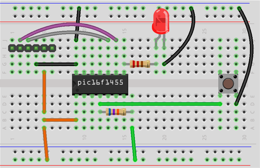
Once the configuration bits have been flashed, the pull-up input switch can be moved from RC3 to RA3, which will work as desired.
Swapping between programming and input pin
Now the trick of moving between functions. Thankfully you don't need to change your code. The configuration bits are already flashed onto the chip.
All that is left to do for programming is to disable the pull-up voltage and the ground wire and re-attach the MCLR wire from the PICkit to the MCLR/RA3 pin. Once your programming is complete, do the reverse: remove the MCLR wire and re-attach the two pull-up switch wires to RA3 and ground.
This is fairly easy to do on your prototype breadboard with the hook up wire, but it might be worth including some kind of switch out on your final PCB design if you wish to program directly on the product board at a later stage.
As an alternative to the above: if the DIP package version of the PIC16F1455 is used, a socket can be added so that the IC is able to be programmed off-board and swapped in.
Summary
I hope this helps serve as a reminder when you are running low on easily accessible GPIO and need to dip into the shared pins. It presents an interesting challenge to work around constraints; to be able to use every part of the chip in your design without having to resort to choosing a larger device.
References
- The breadboard diagrams in this article are done using the excellent fritzing package.
- The IC pin and datasheet illustrations are taken from the PIC16F1455 datasheet from Microchip.