Table of Contents
Repairing an Adafruit Grand Central M4
 A while back, my friend, Professor McSwivells purchased an Adafruit Grand Central M4. Unfortunately it was dead on arrival, and after being in touch with the staff at Adafruit, they reluctantly refunded the purchase but also banned the account.
Adafruit do much for the maker community but their leadership seem fairly petulant when responding to DOA claims as their reputation shows.
The dead board went into a drawer and was forgotten.
The professor recently found it again and thought he'd send it down to me on the off chance that it could be repaired or at least parts salvaged and recycled.
The board arrives
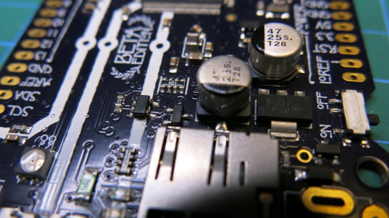
I collected the post and opened it up. Really lovely board, and a stack of pinouts and features. The board sports a SAMD51P20A microcontroller at 120MHz. It contains 1MB of flash and 256KB of RAM. There are 70 pins available, 15 of these are analogue. It uses UF2 which is also what the Raspberry PI Pico uses for programming. You can see all the features here: https://learn.adafruit.com/adafruit-grand-central
I knew the board was basically dead as a doornail, but I plugged in a micro-usb cable from The Grand Central to the PC but no LEDs lit up, and there was no activity on the PC.
The board is all surface mount and so my first challenge was that I don't have much in the way of tools for surface mount. My soldering iron tip is like a sausage compared to the components on this PCB, no soldering tweezers or hot air station.
Fault finding
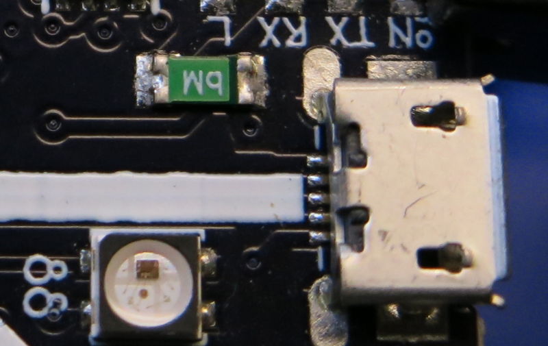
My first step was to test if I could read +5V at the micro USB connector. Yep, I had 5V there at the pin. So that rules out a damaged connector, or not being connected properly to the PCB.
The next was to trace the 5V line. From the USB 5V pin, a trace ran through a small fuse. Testing the fuse with a continuity test, that was fine and I got 5V on either side of the fuse.
From here, it got tricky. The trace ran down and under the micro SD card connector and was hard to see where it came out. I really needed a schematic. Does Adafruit supply schematics?
The Schematic
A simple search showed that Adafruit do indeed supply both a schematic and pcb layout on github in Eagle CAD format. For that, at least, I am grateful.
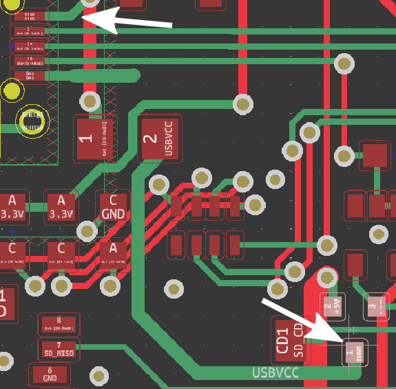
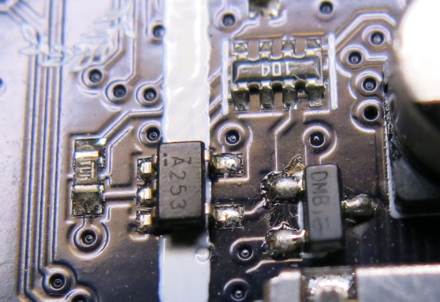
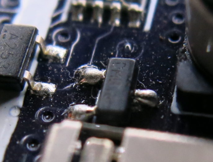
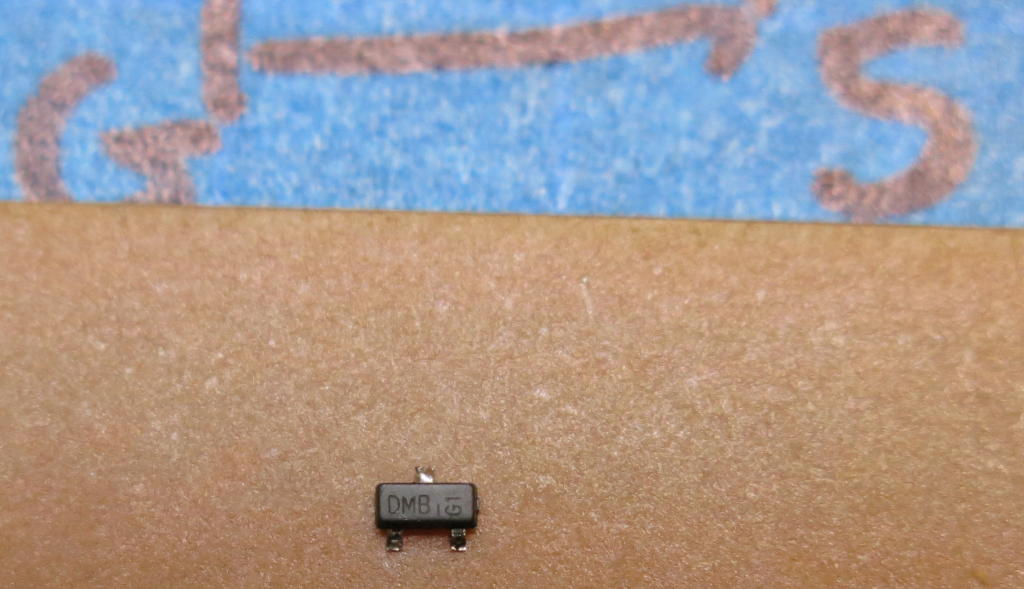
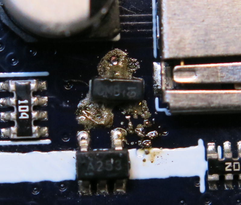
I managed to import this easily into KiCad to see the top and bottom traces. I could see that the 5V line was travelling to the Drain pin of a DMP3098L-7 MOSFET marked DMB. Checking continuity between this pin and the fuse, I expected a connection, but there wasn't any. This can't be a fault with the MOSFET, this is the connecting trace itself.
Tried a number of times, but no success: there was no connection between these points. Could the trace be cracked or partly missing?
Looking with magnification on the MOSFET, it did appear to be slightly offset from it's reference designator printed on the board. And also appeared to be slightly lifted? Could have just been my eyes. Is there a chance that the Drain pin was not connected to the pad and the Source and Gate pins were anchoring it up?
Testing the MOSFET itself with the multimeter in diode mode showed that it looked OK.
Desoldering the MOSFET
This was a little tricky but got done. I used a thin blade to slip under one corner of the the MOFSET while touching the tip of the soldering iron on the Drain, then oscillating the iron between the Source and Gate pins. Once I got a tiny bit of lift, I did the same on the Drain. Back and forth until the MOFSET came off.
I removed the excess solder with braid and cleaned up the area with some isopropyl. Then I placed the MOSFET onto a strip of braid and heated the pins to remove any excess solder under the pins themselves. Probably an unconventional technique, but it worked fine.
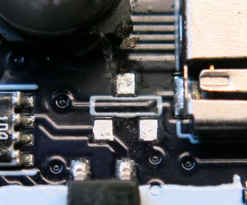
Once the component was off the board, I found that the trace was fine. There was continuity between the Drain pad and the fuse.
Resoldering the MOSFET
I applied solder paste to the three MOSFET pads with a toothpick and placed the component down with tweezers.
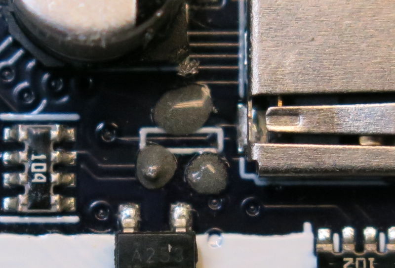
Using the soldering iron, I touched each pad carefully to melt the solder paste. The result was ok, but lots of micro solder balls.
Lightly scraping the area with a point, then cleaning the area with isopropyl brought it up pretty nice. Checking contact between pads and surrounding components showed that there was no incorrect bridging.
And more importantly, the Drain pin was connected nicely to the fuse meaning that I should get 5V now.
Testing
Hooked up the Grand Central to the PC with the USB cable and I got lights! Checking the File Manager under windows and the Mass Storage drive popped up.
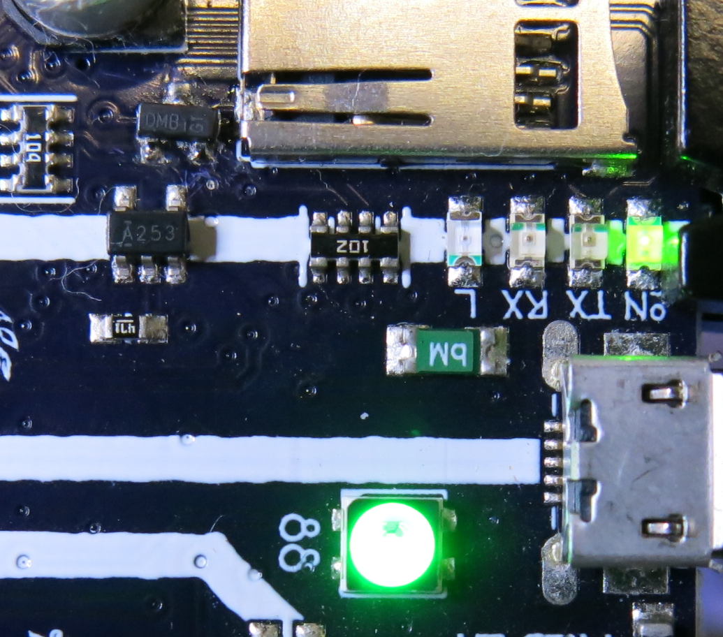
Great Success!
Well that's a win. This was an unlucky board with a misaligned DMP3098L-7 MOSFET from a pick and place machine during board population. This board will come in super handy for some projects.
Based on Adafruit's customer service and leadership's known reputation in regards to shying away from faults, would I continue to support them? They do support the community with tutorials, libraries and reference material. However, I would rather do without: walk the harder road, and support the nicer guys instead.