This is an old revision of the document!
Table of Contents
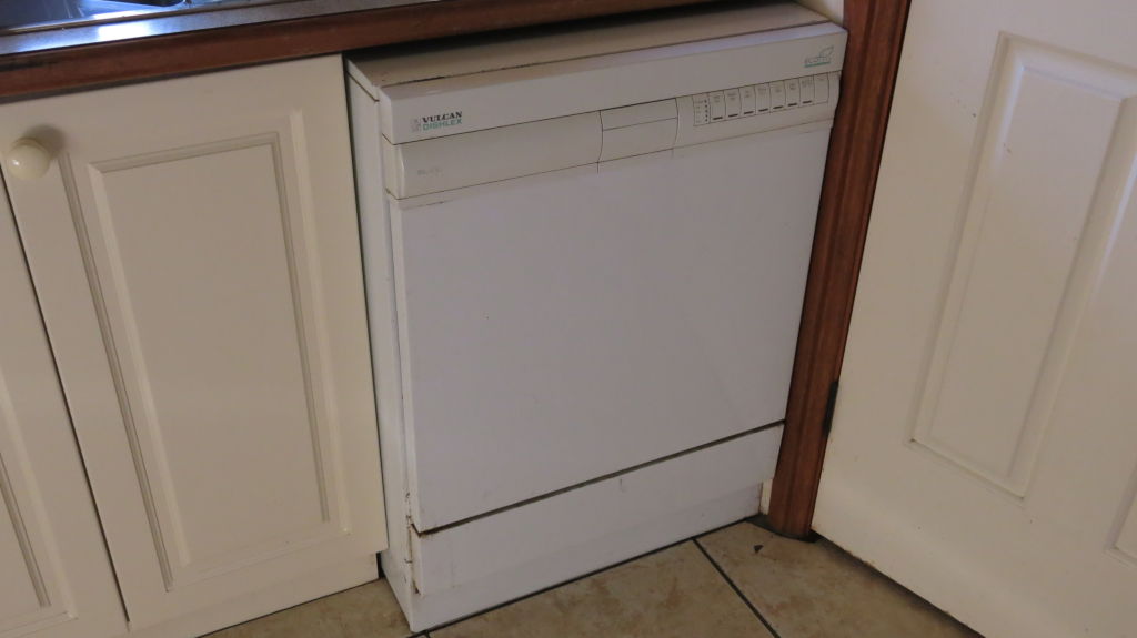
Repairing the Vulcan Dishlex Milano Dishwasher
 Two weeks before the International Repair Day 2021, our 16 year old dishwasher from 2005 packed it in. It came with the house, and was pretty old back then. We never used it all that much over the years. But recently it has been used more, and I guess the old girl couldn't cope.
Symptoms
The first sign of problems was one evening when the wash would stop after less than two minutes. No matter what programme was selected, it would rarely get far.
The machine was switched off and on again after a few minutes. Pressing buttons was somewhat responsive and there were some lights but the machine would not start.
Turning the machine off and back on after ten minutes resulted in no lights, or beeps or any activity.
So the search began online for a new dishwasher but it seems that machines have all gotten taller and fatter over the years (haven't we all), and average dimensions are at minimum 2mm too high to fit in our space.
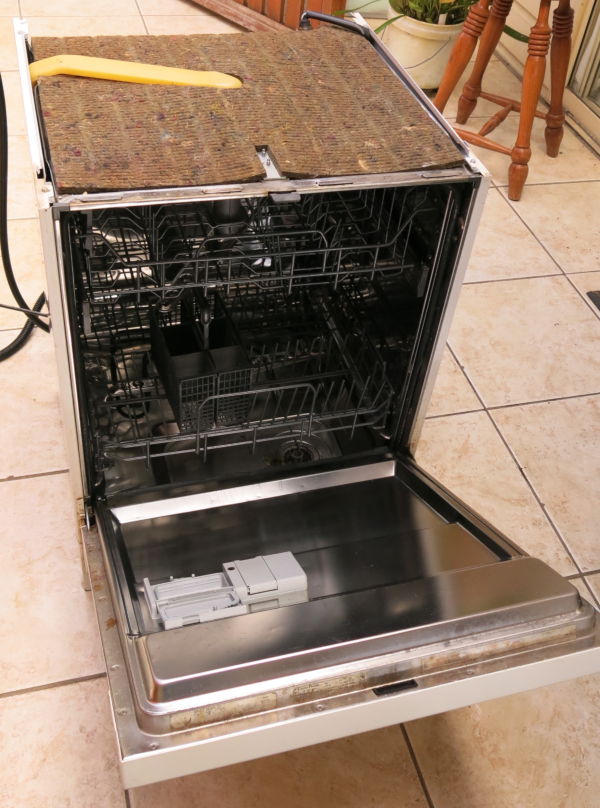
Opening the machine
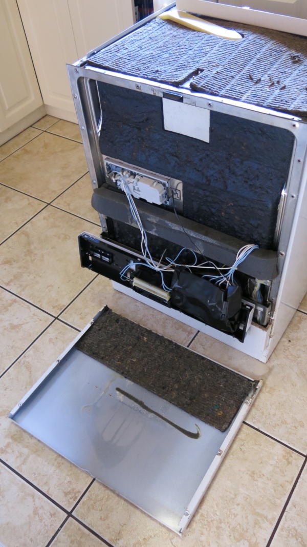
I know nothing about dishwashers (or even how to operate one), so I had really no idea where to begin. So I must confess, for the International Repair Day I just spent the day removing each panel as a way of finding out where everything was located.
I suspected either some logic PCB or power supply would be at fault, but where are they located?
There are no disassembly plans or schematics available online. I can't find any material anywhere regarding a Vulcan Dishlex Milano.
Full disclosure, I opened up way more than I needed to.
At this point I figured it would be prudent to hop onto the Youtubes to look at the basics of dishwasher maintenance, which was a really good idea and gave a good overview of common issues. Perhaps this should have been my starting point.
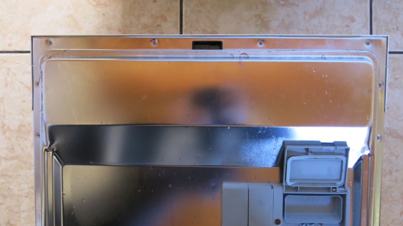
While the machine was apart, I did locate a few key items. I found a sensor on the right that checks when the door is fully open or closed which tested out fine.
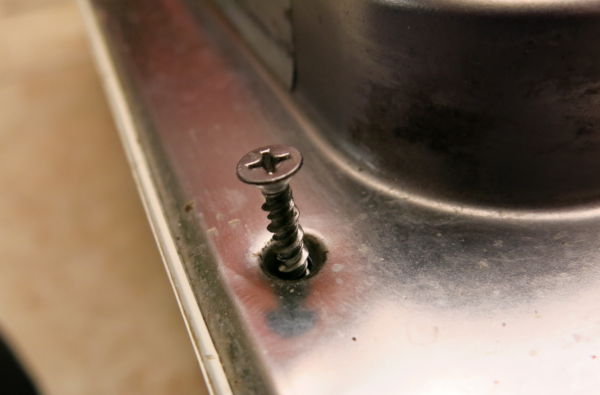
Also, I discovered a machine screw missing from the door hinge. I found a suitable replacement and added that in.
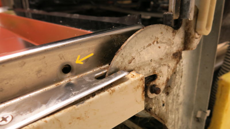
The power features like the 240V line, motor and connections are located at the bottom of the machine, and the logic controller is located inside the door assembly. Turns out I did not need to remove the top cover, the sides, or the back.
So I'll walk through what I did to repair it, and from the assumption that I opened only the front door panel - which was the only area I needed to work on.
Opening the door panel
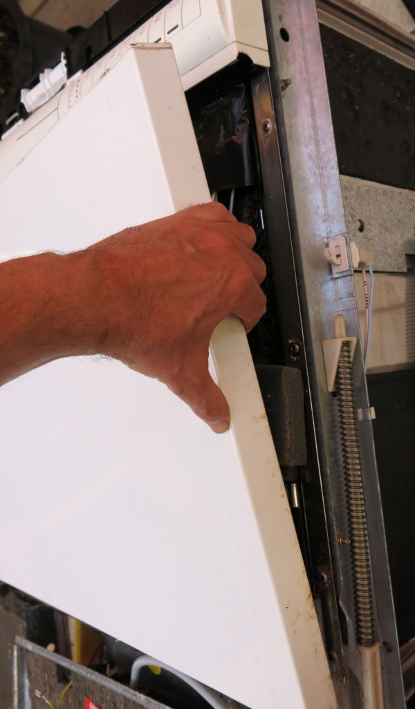
In order to access the control panel and controller PCB, the door assembly needed to be opened. There are 12 screws, of two types. The larger screw at the top of the door and the smaller for the rest. I took careful note and bagged them so they wouldn't be lost.
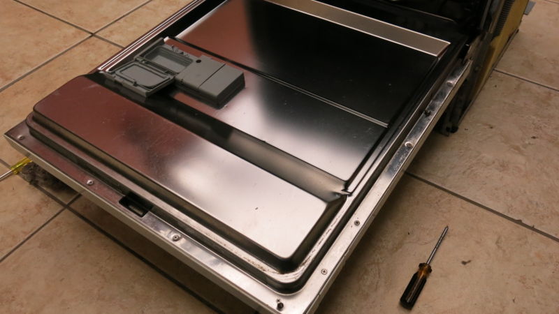
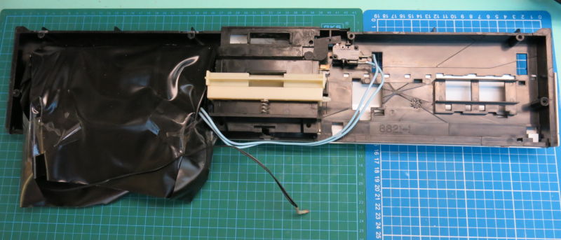
Next was to remove the front panel so that the control panel assembly could be lifted away. The front panel has some adhesive to keep it attached to the door, and in retrospect, I don't think it needed to be removed. As long as there was some leverage, the control panel should still have been removable.
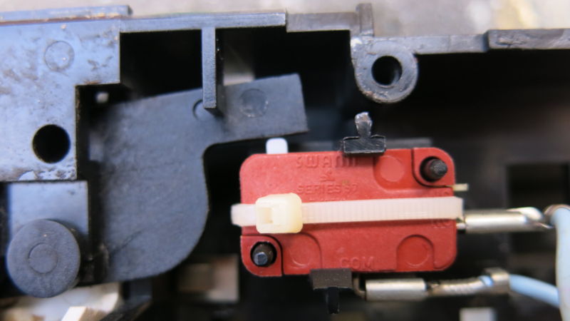
Once the control panel assembly was free of the door, it was still connected to the door with it's wiring harness. I could now see that there was a kind of bag thing, and a microswitch.
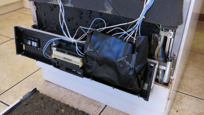
The microswitch is used to tell the controller that the door is fully closed and locked, and washing can safely begin. This was the first component to test.
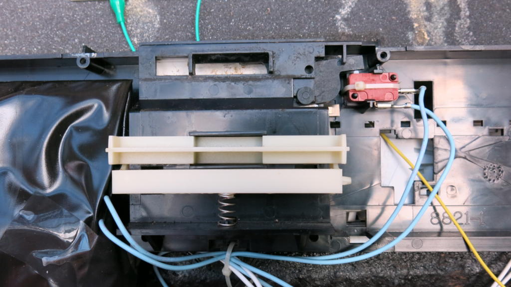
In continuity mode on my multimeter, I found that when the switch was pressed, it made a nice click as a good microswitch should. But unless you pressed it further, there was no continuity. Needed replacing.
Could this repair be as simple as that?
I dug out a few spare microswitches, mostly some cannibalised good brands with a high voltage rating. One was a new switch for my pinball machine projects, but I don't know the rating for that one.
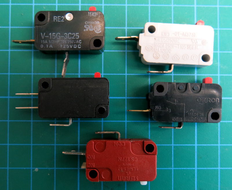
Also the white microswitch was a normally closed switch. Gotta test your spares. Settled on one, and swapped the switch out.
Tested beautifully.
Perhaps it was just a faulty door switch stopping the wash from working.
After re-assembling, I hooked up the water and power.
Switched on. Pressing buttons, no sound, no response. Seemingly nothing.
Symptoms #2
I left the machine for a couple of minutes with it's door open while I was distracted with something else.
I heard a noise like a cricket, fast chirps getting faster and louder. What on earth was that? It's the dishwasher!
The chirps slowed down and stopped. Ok that was weird. Pressing a button would flash the light on that button really fast and more fast chirps. Also some rapid relay switching of the motor. That didn't sound good.
Switching off and on again would produce more weirdness, slightly different each time.
Right so it's more than the door switch. It's really starting to smell like dying capacitors or dry joints.
Opening up again
Disassembled the door assembly again and took another look at the bag. This contains the controller PCB. I could actually see into the bag from the bottom. It looked pretty clean from what I could tell.

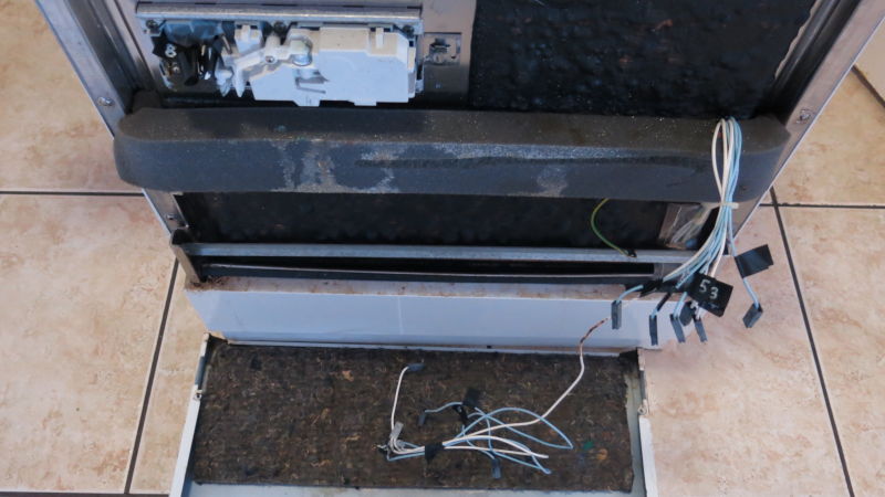
There are nine connector to the wire harness. I would need to remove the harness to free to controller assembly and get it into the workshop.
Here's where my planning and a little insurance became a life saver.
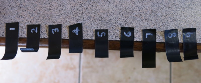
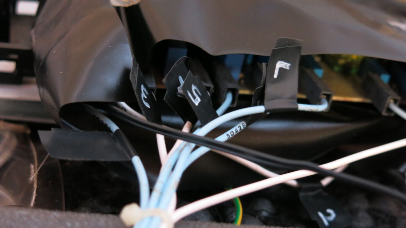
There was no way I was going to know which wire went onto what connector when there were 13 wires and only two colours: blue and white.
I cut up strips of black electrical tape with numbers written on them in white marker. These were then used as labels to mark the wires so I could find my way back at re-assembly time.

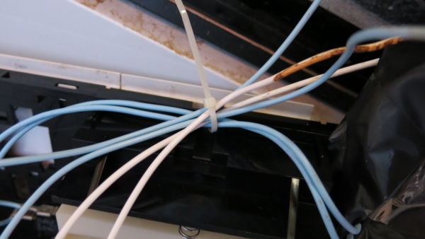
I also needed to remove the tie that binds the wires. I took note of the tie position so I could replace it and re-bind the wires later.
Once the wires were disconnected I was able to get this onto the workbench to get a decent look at how to get the PCB out of the bag and off the controller assembly.
I removed the front cover of the control panel releasing the binding clips which revealed the control panel PCB.
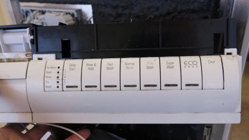
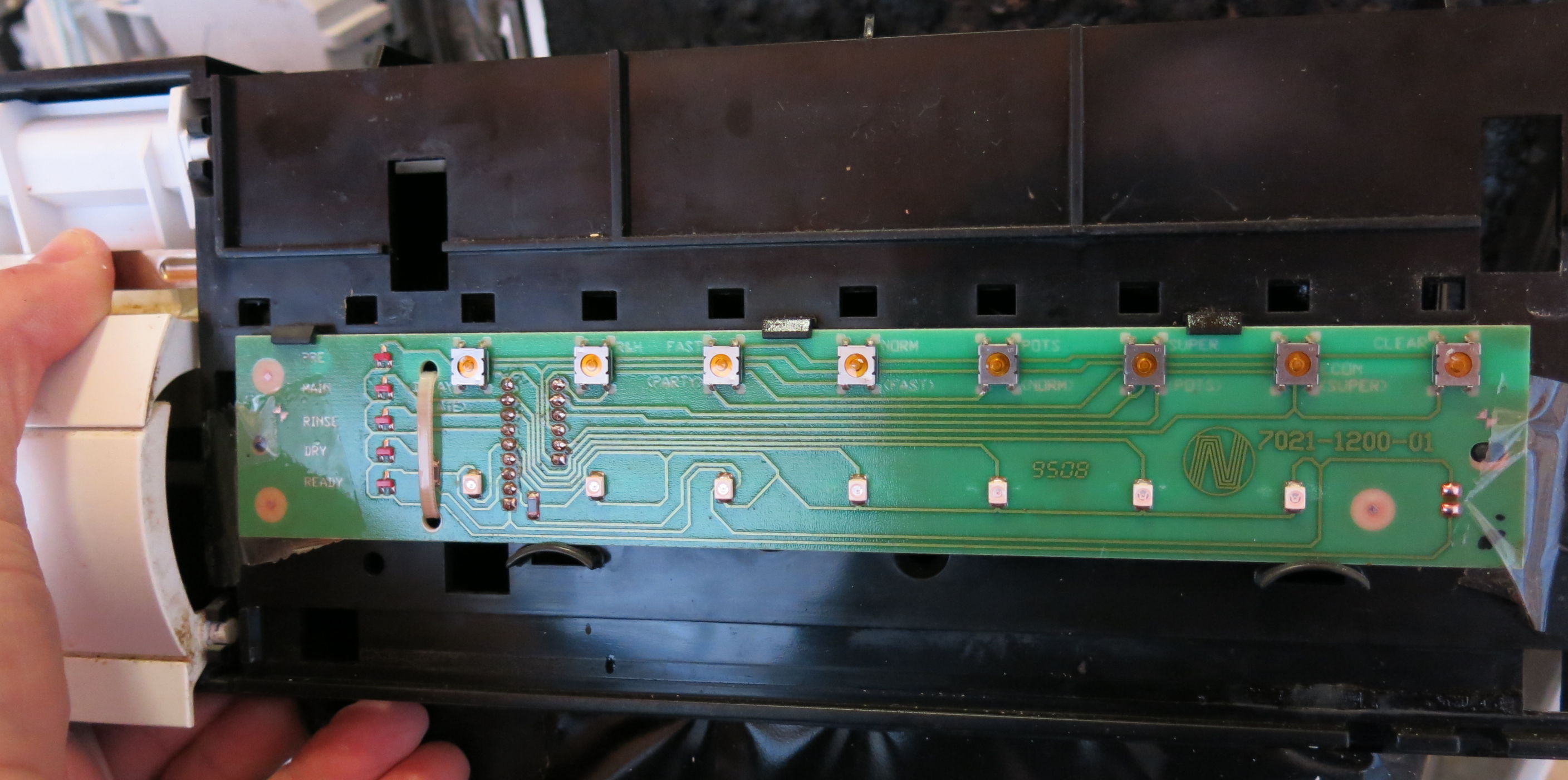
I managed the test the continuity of the button switches and they were fine. One was a little mushy but worked fine, and I didn't have spares so I left it alone. All LEDs were fine.
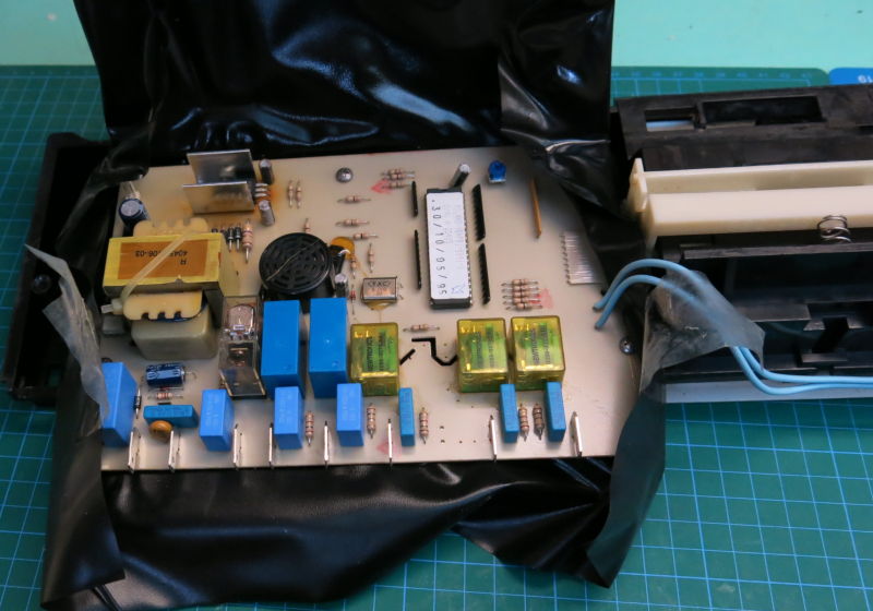
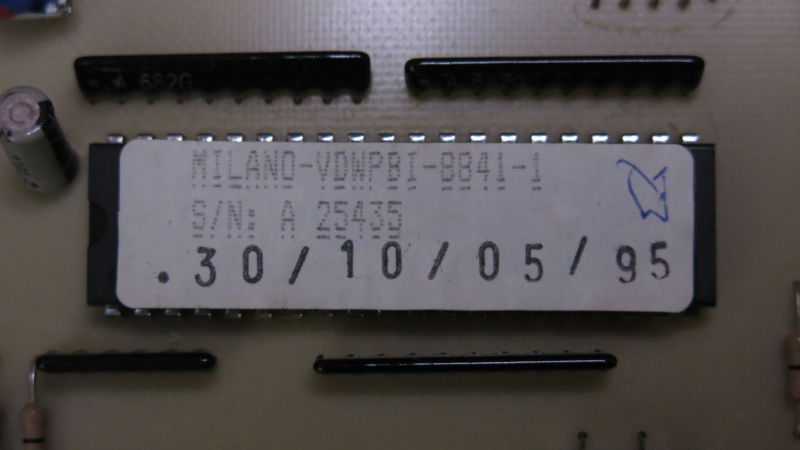
There was a couple of pieces of tape on the bag and once peeled back the bag opened up revealing a fairly simple and clean PCB featuring a Milano EPROM or controller IC. Very cool.
Once the bag was open, I could see three screws holding the PCB to the assembly.

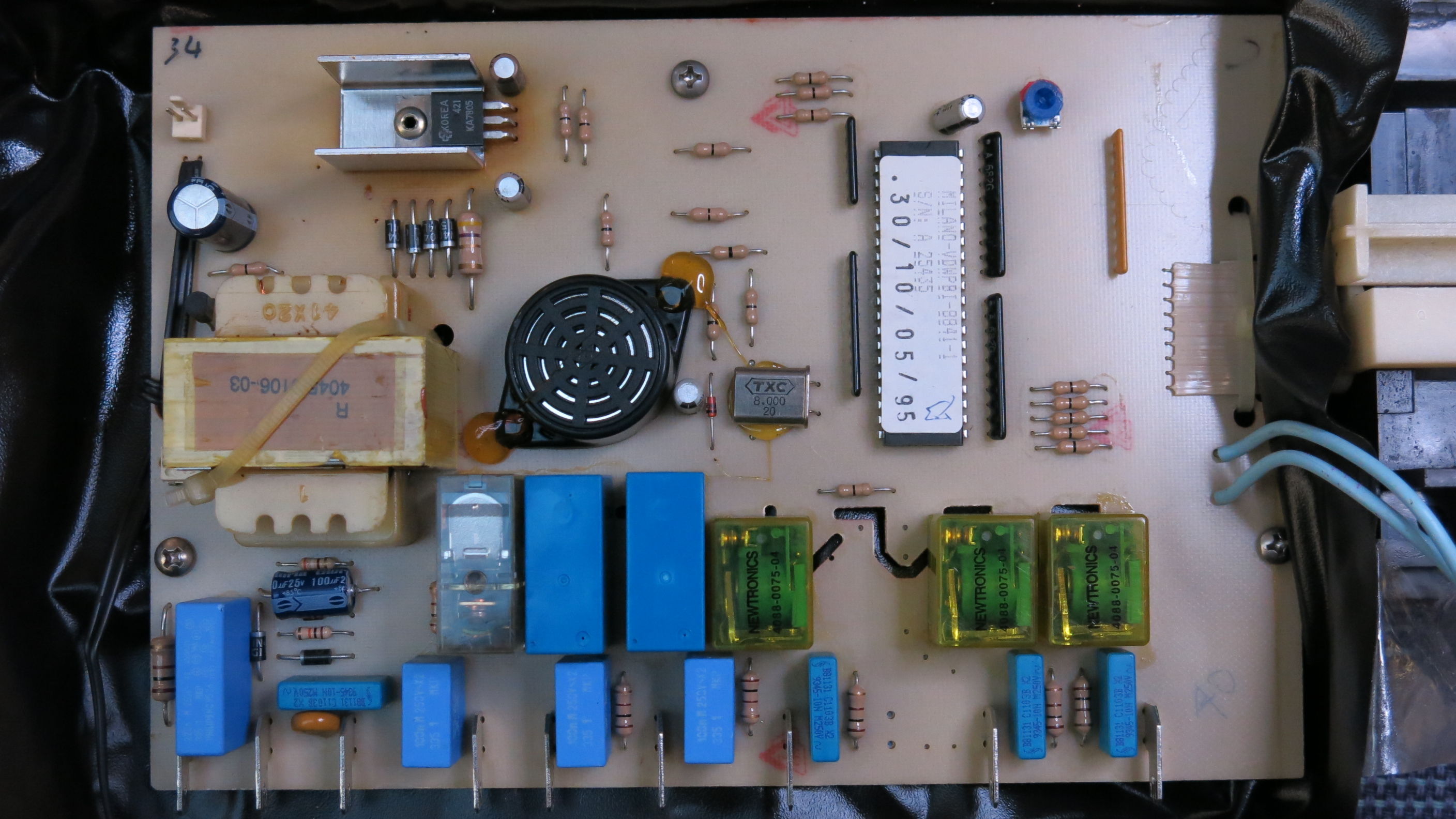
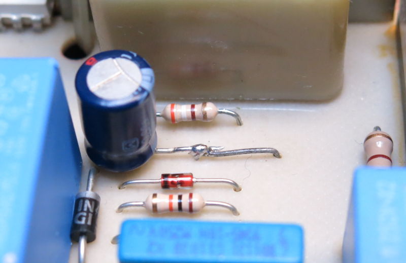
First thing to test was the common easy stuff like the resistors, diodes and the coils in the relays. They all tested out fine. Inspection of the solder on the rear of the PCB showed up a really nice clean board. All seemed pretty good.
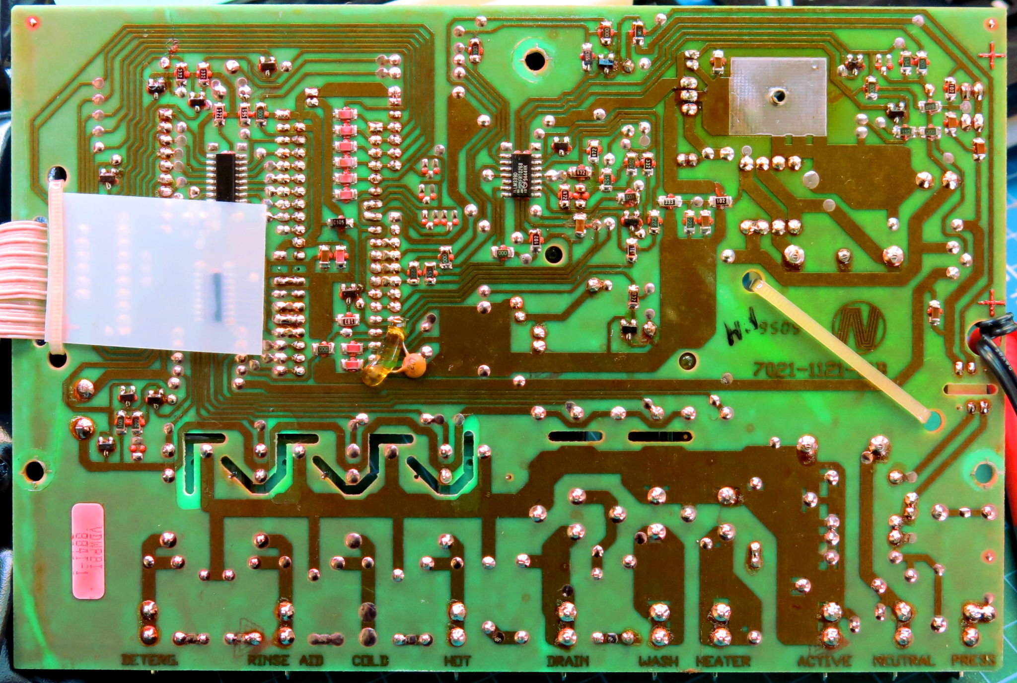
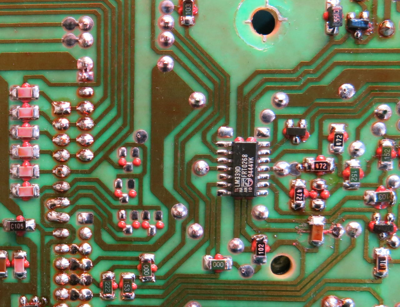
An interesting side note is the way the surface mount components were added to the PCB in the factory. Little blobs of what looks like red glue have been used to fasten the components down. I can only imagine this has been a partly manual process instead of the usual pick and place machine? I'd be interested to hear from anyone if they have seen this before and know what it is about.
Capacitors
Time to move to the capacitors.
I started with all the blue MKT caps along the bottom of the board. I tested in-circuit on the PCB. The 220nf showed as around 180nf. The three identical 100nf caps tested as 90nf, 37nf and 23nf. The smaller remaining 10nf caps seemed ok at 8nf.
But the 220nf and the three 100nf needed re-checking as it seemed like parallel components might have been throwing those measurements out. I de-soldered and re-tested and sure enough, those readings on the board were true.
The 90nf was pretty close but 37nf and 23nf for a 100nf cap is way out of spec and a pretty good reason for the weird behaviour the dishwasher was exhibiting.
The 220nf was close enough.
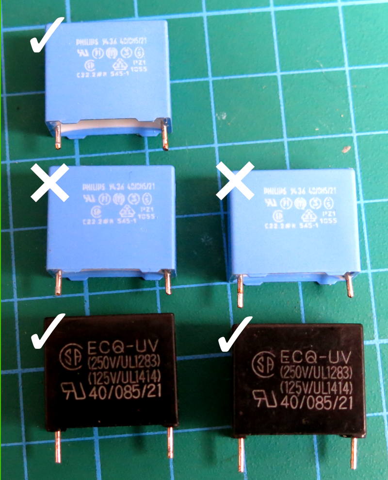
Thankfully I found two replacement 100nf MKT caps from some junk boards.
Next up was the 1000uf 25V electrolytic capacitor. With my multimeter, the reading was pretty low so I popped it into the GM-328 for a second opinion.
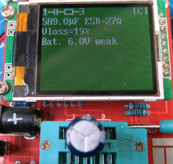
Woah. Nearly half at the 590uf mark and a blistering 27 Ohms of ESR. That's a really bad cap and completely out of spec.
The replacement was a touch over 1000uf and a lovely 0.7 Ohms ESR.

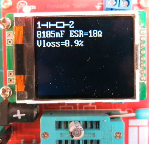
Next, the four 10uf 25V electrolytics. Each was close to 10uf but again, ESRs varying from 10 to 18 Ohms. Smaller caps do have a higher ESR, but those numbers are just too high.
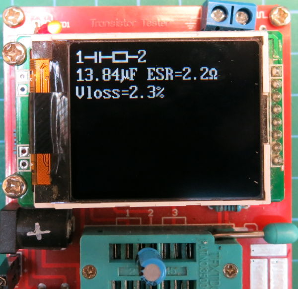
I replaced them with cannibalised replacements with ESRs around 2 Ohms.
Finally, there was the ?uf axial capacitor. I wasn't happy with the result of that one either. It came in at ???.
I had a replacement which read as: ??? which was much better. However it wasn't an axial part. So I had to be a little creative. I used the leg of a rubbish Suntan capacitor to extend the negative leg of my replacement.
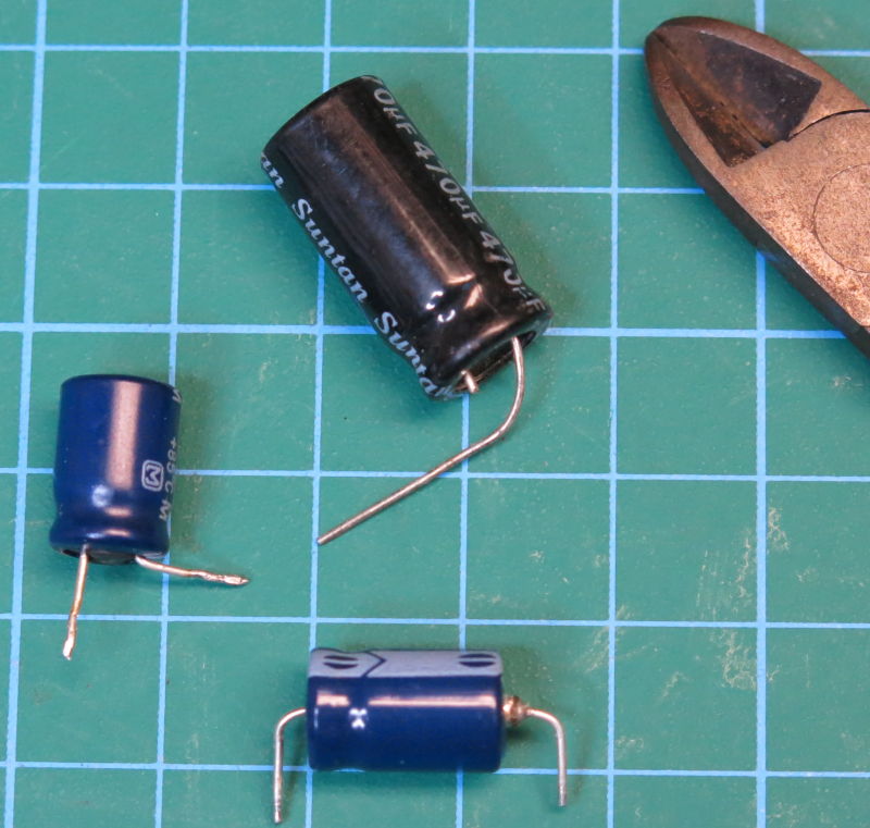
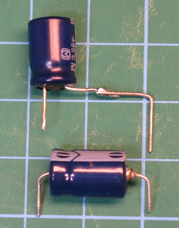
Not super neat but it worked fine.
Voltage Regulator
When first inspecting the PCB, an area was discoloured around the KA7805 regulator and it's headsink. It must have worked pretty hard over all these years. So it was worth checking that it was operating well.
Rather than remove the component, it was easier to solder wires to the legs, and power it using a bench power supply.
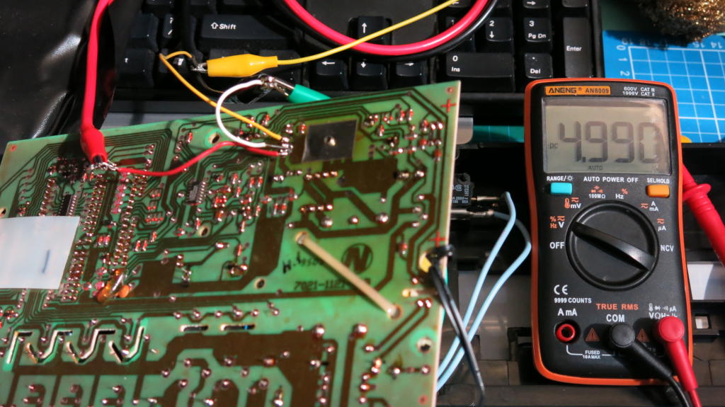
I tried a variety of voltages from 5 - 8V and the output was a steady 4.5 - 5.0V. Happy with that, so I re-soldered the hookup wires and left it alone.
Re-assembly and Test
The difficulty with a repair like this is that there is no way to do fast test iterations. You need to fix everything you can think of before committing to re-assembly and checking.
At this point, it was just a case of re-assembling the controller assembly and re-assembling the front door assembly.
Even though that's one sentence it still took a mighty long time to carefully re-attach all the connector wires in the right order and place the front panel and controller assembly back on.
But once done it was time to hook up the power.
When switching on, no lights as standard, but opening the door gave a cheery beep. That's a good sign. No weird chirping either.
Pressed one of the delay programmes and it lit up with a nice beep. I cancelled it as I didn't have the water hooked up yet.
All good signs so far. At this point I felt confident to connect the water supply and drain pipes and try to see if the machine would respond to a fast wash. Pipes connected and fast wash started…
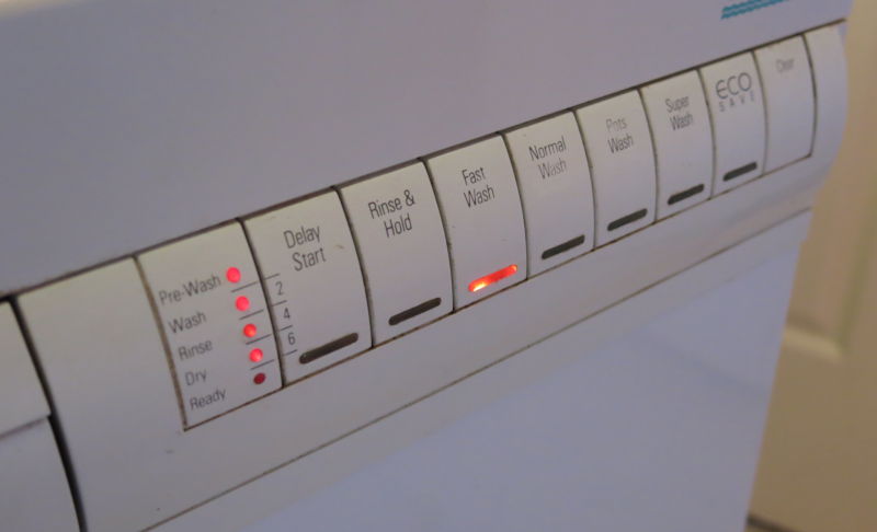
It worked!! Happy day.
Conclusion and Lessons Learned
This was a real education, important lessons and takeaways from this repair:
- Get some experience watching similar repairs. You'll get a better feel what what you're about to embark on.
- Take photos as you go. Loads of them. They are your “get out of jail” cards.
- Mark wires and where they go. Don't think you will ever remember.
Having expected to have to buy a brand new dishwasher, now we can get a bit more life out of this one. My wife thanked me for all my efforts. Though I couldn't help noticing her teeth might have been gritted at the time.
Jokes aside, it does buy us some time to keep an eye out for a unit to replace it with in the future when it's no longer feasible to repair.
We did enjoy pouring a drink and together watching the machine go through it's entire cycle. COVID entertainment at it's finest.